Quick Links
Feel free to click on one of the links in this section to jump to the material you are looking for:
Introduction Quickstart Guide Floppy Drives Hard Drives
Miscellaneous Downloads Table of Contents Contact Details
Introduction

DEC made a series of “RQDX” controllers back in the day. These are known as the RQDX1 and RQDX2 (both are quad-height QBUS boards with M8639 on the handle) and the RQDX3 (which is a dual-height QBUS board with M7555 on the handle).
The RQDX controllers allowed a limited number of models of industry-standard Winchester (MFM) Hard Drives and certain 5.25″ floppy drives to be used on a QBUS PDP-11 or MicroVAX system. The number of supported models of hard drives and floppy drives increased as each subsequent RQDX controller was released.
These controllers are attractive in some ways. In particular, they are an easy and cheap way to add a bootable drive (hard drive or floppy drive) to a compact or cobbled-together benchtop PDP-11 system. But the performance is pretty lousy. Booting RT-11 from floppy on an RQDX controller is about as fast/slow as booting from an emulated TU58 drive over a spare serial port on the PDP-11 at 38,400 baud. Booting from an MFM hard drive is a little quicker. But of course it’s getting to be more difficult to find a reliable MFM hard drive now, given the age of those drives.
A further limitation is that the RQDX boards don’t contain a boot ROM (to allow the RQDX board to boot from a cold start), so you need to have another board installed in the QBUS backplane that has boot ROMs, or be prepared to type in a fairly long bootloader at the console on start up.
If you are disappointed in the performance of the RQDX controllers and can afford the expense, you might want to consider using RL drives instead (real or emulated), or a QBUS SCSI card connected to a SCSI2SD hard drive emulator, to overcome some of these limitations.
This webpage is something of a war-and-peace brain dump of what I have learned about using the RQDX controllers. It also describes my “RQDX Breakout Board” (aka “RQDX BOB”) that I cobbled together to assist with interfacing the RQDX controllers to hard drives and floppy drives. This is unfortunately necessary as the 50-pin connector on the RQDX controllers can’t be connected directly to any drive.
DEC’s Breakout Boards
I am aware of two “breakout board” wiring schemes that were used by DEC to connect an RQDX3 to its drives:
- BA23 Enclosures: A BA23-A breakout board (assembly P/N 70-1998600) is mounted on the reverse side of the H9278A QBUS backplane
- BA123 Enclosures: An M9058 “RQDX Signal Distribution Board” (dual-height QBUS board) was plugged into the QBUS backplane

BA23-A: The BA23-A breakout board is shown in the picture to the right. I haven’t been able to find a schematic for the BA23-A breakout board, or reference to the existence of any publicly-available schematic.
Interestingly, it has no electronic components on it other than a variety of header sockets. It does connect to a front panel that has ready and write-protect LEDs and switches. There are no configurable jumpers on the BA23-A.
The large 50-pin header (with latches) connects to the RQDXn controller in the QBUS backplane. The 20-way and 34-way headers connect to hard drives and/or RX50 floppy drive in the drive bay. The 10-pin header connects to the ready and write-protect switches and LEDs on the front panel. This 10-pin header (J4) is not to be confused with the 10-pin header that is mounted directly on the H9278A backplane. The latter is used for control signals required by the QBUS boards (BDCOK, BEVNT, BHALT, etc), some of which are generated by the front panel circuitry and switches.

M9058: The M9058 is an interesting and useful board. On the front side of the M9058 are:
- 4 pairs of headers to connect up to 4 MFM hard drives. These are marked RD0 through RD3
- A single 34-way header to connect to an RX50 floppy drive. This is marked “RX50”
- A single 40-way header to connect to front panel switches and LEDs
- Various logic and buffer ICs, to distribute the RQDX signals

On the rear side of the M9058 there is a 50-way header to connect to the RQDX3 board.
Note that the M9058 has dedicated 34-way “control” headers for each hard drive. This differs from the usual design approach of daisy-chaining the “control” cable between the controller and each hard drive.
When used in the BA123 enclosure, the M9058 is not installed in the main (forced ventilation) card cage. Instead, it plugs into a QBUS slot that is positioned outside the main card cage. It probably could be installed inside the card cage, but be aware that because of the various header connectors on the M9058, it will probably occupy about 4 slots.
If you are planning on using an M9058, you will find the schematics for it in the RQDX3 Field Maintenance Print Set (MP-02259). See pages 8 to 13 of that PDF.
RQDX Breakout Board

The RQDX BOB provides the circuitry needed to interface an RQDX controller to:
- Standard 3.5-inch floppy drives, emulating DEC RX50 (400KB) drives
- Standard 3.5-inch floppy drives, emulating DEC RX33 (1.2MB) drives
- Selected (DEC compatible) MFM hard drives, such as the Seagate ST-225 or ST-251
The board enables standard PC-era 3.5 inch floppy drives to be used without any modifications, even though these drives require non-standard cabling (remember the “twist” in pins 10 to 16 of the 34-way cable?), are hard-wired to respond only to the Drive-Select signal appearing on Pin 12 (rather than each drive having drive-select jumpers), and output a “/Disk Change” signal (rather than a “/READY” signal) on Pin 34.
With a little effort, the RQDX BOB can also use 5.25-inch HD (1.2MB) floppy drives instead of 3.5-inch HD (1.44MB) drives. The board should also enable floppy-drive emulators and MFM-hard-drive emulators to be used with an RQDX controller, though I’ve not yet tested or verified this.
The circuit diagram for the RQDX BOB and extensive notes are also provided below.
Quickstart Guide
If you are keen to plug in and use the RQDX BOB without digging too deeply into the background theory, here are some instructions that should get you up and running fairly quickly:
- Check that your RQDXn controller is properly configured for your PDP-11 system.
- If using an RQDX3 controller, configure Jumper W23 (which is adjacent to Pin 1 of the 50-pin connector) by inserting a jumper between Pins 2 and 3 of this 4-way jumper. This routes the RQDX3’s “Head-Sel-3” signal to Pin 9 of the 50-pin connector. Often you will find that Pins 1-2 are connected instead (Pin 1 is closest to the QBUS edge connector). If Pins 1-2 are linked, the Head-Sel-3 signal will instead be routed to Pin 22 of the 50-pin connector.
- No specific configuration changes are required on an RQDX2 controller.
- Configure the jumper settings on the board as specified under the heading “Board Jumper Settings” below. Use “Standard RQDX2 Configuration” or “Standard RQDX3 Configuration”, as applicable.
- Connect the board to the RQDX controller using 50-way cable fitted with standard IDC 50-way sockets (BERG connectors are not required).
- Connect one or two standard/unmodified 3.5-inch HD floppy drives to the board using a “twisted” 3-connector 34-way data cable. All 3 connectors should be IDC 34-way sockets. These are the cables that were commonly used in PCs during the period 1990-2005. They have conductors 10 to 16 reversed at the “Drive A” end of the cable. The mid-cable connector was for “Drive B” and connects all conductors straight-through to the controller end of the cable. If using only one drive, connect it to the “Drive A” connector at the end of the cable (ie – so there is a “twist” between the single drive and the board).
- If connecting an MFM hard drive, connect that drive to the board using “straight through” 34-way data cable (for the control signals) and a 20-way data cable (for the read/write data signals). Each cable should have an IDC socket at one end and an IDC edge connector socket at the other end. Install the “DS0” jumper on the MFM hard drive and remove all other drive-select jumpers.
- Supply power to the drives and the board. This can be done using a PC power supply (it will need to be modified to turn on without a motherboard connected), by using the GND, +5V and +12V terminals on the PDP-11’s inbuilt power supply, or by using an external power supply of some sort. The board uses the same power connector as is standard on 3.5-inch floppy drives. Note that 3.5-inch floppy drives, and the board, do not require the +12V that is provided on the standard connectors. But it will not do any harm for +12V to be present on the connector. If needed, floppy drive cabling (adapters, splitters, etc) are still fairly easy to obtain on eBay.
RQDX BOB Jumper Settings
Most of the configurable jumpers on the RQDX BOB relate to floppy-drive functionality. If you are using a “standard setup”, then the jumper settings shown in the “Standard Setting” column should work for you. By “standard setup”, I mean:
- You are using no more than two physical floppy drives.
- Your floppy drives are unmodified PC-era 3.5-inch HD (1.44MB) drives.
- The floppy drives are connected to the RQDX BOB with a data cable that has pins 10 to 16 “twisted”.
- You are expecting your RX50 disks to be single-sided only (ie – the second side is unused).
Significant variations from this “standard setup” are possible. The notes in the “Commentary” column explain the possibilities in some detail.
| Jumper | Standard Setting |
Commentary | |
|---|---|---|---|
| JP1 | REMOVED | With this link REMOVED, Floppy Drive A is selected only when RQDX DS1 goes low. This configuration is appropriate when the floppy drive is intended to emulate a normal (ie single-sided) RX50 or a normal (ie double-sided) RX33. If this link is INSTALLED, Floppy Drive A is selected whenever RQDX DS1 or RQDX DS2 goes low. This configuration is appropriate when Floppy Drive A is to be used as two RX50 drives (ie RQDX DS1 accesses Side 0 of the disk, RQDX DS2 accesses Side 1 of the disk). | |
| JP2 | ON | With this link installed, when the RQDX’s DS2 signal goes low then Floppy Drive B’s Drive-Select signal will be pulled low. This is the “standard” configuration for the RQDX BOB. If you instead want to configure Floppy Drive A to be a double-sided RX50 drive, JP1 should be IN and JP2 should be out. | |
| JP3 | OFF | With this link OUT, the RQDX’s DS3 signal is not connected to the floppy-drive-select logic (and DS3 can therefore instead be used for an MFM hard drive). This is the “standard” configuration for the RQDX BOB. With this link INSTALLED, the RQDX’s DS3 signal is instead used to drive Floppy Drive B’s Drive-Select signal. | |
| JP4 | OFF | With this link OUT, the RQDX’s DS4 signal is not connected to the floppy-drive-select logic (and DS4 can therefore instead be used for an MFM hard drive). This is the “standard” configuration for the RQDX BOB. With this link INSTALLED, when the RQDX’s DS4 signal goes low, the Drive-Select signal for Floppy Drive B will be pulled low. Normally JP3 and JP4 would only installed when you are using two double-sided RX50 drives (and therefore allocating DS1, DS2, DS3 and DS4 to the floppy drives). | |
| JP5 | 2-3 | With Pins 2-3 linked, when the RQDX’s Head-Sel-0 signal goes low, the “Side Select” pin on the floppy drives (Pin 32) will be driven low, allowing access to the second side (upper surface) of the floppy disk. This is the “standard” configuration for the RQDX BOB, and allows both double-sided RX33s and single-sided RX50s to be used in any combination and in either position on the “twisted” floppy drive cable. If you are planning to configure Floppy Drive B as a double-sided RX50, then you must instead install a link between Pins 1-2, so that Floppy Drive B’s Drive-Select signal is driven low when the RQDX’s DS4 signal goes low. Note that if you want to use a double-sided RX50 and an RX33 on the RQDX BOB at the same time, then Floppy Drive A must be the RX50, Floppy Drive B must be the RX33, and this link must be in the 2-3 position. | |
| JP6 | RQDX3: 1-2 RQDX2: 2-3 |
This jumper relates to Pin 9 of the 50-pin cable connecting the RQDX controller to the RQDX BOB. The signal carried on that pin varies depending on the controller (RQDX2/RQDX3) and, for the RQDX3, how Jumper W23 is set on the RQDX3 controller. | |
| When using an RQDX2, a jumper must be installed between Pins 2-3, to pull the RQDX2’s “DRVBUSOE” input low. Without this jumper in place, the RQDX2’s outputs are disabled, and none of the drives connected to the RQDX BOB will work. | |||
| When using an RQDX3, the 2-3 jumper must be removed, and a jumper should be installed between Pins 1-2, so that the RQDX3’s “Head-Sel-3” signal is available to the MFM hard drives. Note also that on the RQDX3 controller board, Jumper W23 (which is adjacent to the 50-pin connector) must have a jumper installed between Pin 2-3, so that the RQDX3’s “Head-Sel-3” signal is routed to Pin 9 of the 50-pin connector. “Head-Sel-3” is only required for hard drives having more than 8 heads, so often it will not be required. | |||
| JP7 | REMOVED | With this Jumper REMOVED, the floppy drive’s MOTOR ON signal will be controlled by the RQDX controller and the 555 timer on the RQDX BOB. With this Jumper INSTALLED, the floppy drive’s MOTOR ON signal will be pulled low continuously by the RQDX BOB, with the result that the floppy-drive motors will run continuously. This Jumper is intended for testing purposes only, and generally this Jumper should be left REMOVED. | |
| JP8 | RXDX3: INSTALLED RQDX2: REMOVED |
With this Jumper INSTALLED, the floppy drives are able to pull Pin 34 low. When using PC-compatible 5.25-inch or 3.5-inch floppy drives, this signal will be a “/Device Change” (“/DC”) output from the drive. Note that prior to the PC era, floppy drives instead used this pin as a “/READY” output from the drive. | |
| When using an RQDX2: An RQDX2 expects the floppy drive to output a /READY signal on Pin 34, rather than a /DC signal. So if using PC-compatible floppy drives you will need to REMOVE JP8 (to prevent the /DC signal reaching the RQDX2), and INSTALL JP9 and JP10 (so the RQDX BOB can create fake /READY signals for input into the RQDX2). If you are instead using floppy drives that output a /READY signal on Pin 34, then INSTALL JP8 and REMOVE JP9 and JP10. | |||
| When using an RQDX3: An RQDX3 expects that any double-sided floppy drive connected to it will output a /DC signal on Pin 34, regardless of whether the drive is operating in DS-HD mode (ie RX33) or SS-DD mode (ie RX50). So always INSTALL JP8 and REMOVE JP9 and JP10. Note that the RQDX3 has a clever technique for working out whether it has a “real” RX50 attached, or whether an RX33-compatible drive is operating in DD (ie RX50) mode is attached, and adjusts its expectations as to what it expects to see on Pin 34 accordingly. This is described further below under the heading XXXX. Because of this, drives that output a /READY signal on Pin 34 (other than perhaps a “real” RX50 drive) will probably not work on the RQDX BOB. | |||
| JP9 & JP10 | RQDX3: REMOVED RQDX2: INSTALLED |
With these Jumpers REMOVED, the RQDX BOB does not attempt “fake” the /READY input (Pin 50 of J12) to the RQDX controller when DS1 or DS2 is pulled low by the RQDX controller. Instead, it is assumed that JP8 will be installed, and the /READY input to the RQDX controller will come directly from Pin 34 of the floppy drive. If Jumpers JP9 & JP10 are INSTALLED, the RQDX BOB automatically pulls the RQDX’s /READY input line low whenever the RQDX controllers pulls the DS1 or DS2 line low. The RQDX BOB does this regardless of the floppy drive’s real status. See the commentary above relating to JP8 for related comments. | |
| JP11 | REMOVED | This Jumper selects the signal/voltage that the RQDX3 applies to Pin 2 of the floppy drive cable. With this Jumper REMOVED, the Pin 2 input to each floppy drive is floating high. With a Jumper between Pins 1-2, the RQDX controller’s “TG43” output is sent to Pin 2 (this is used by a real RX50 to reduce the drive’s write current for tracks greater than 43). With a Jumper between Pins 2-3, the Pin 2 input to each floppy drive is pulled low by the RQDX BOB. | |
| 3.5-inch HD drives: Generally speaking, most 3.5-inch HD drives ignore the Pin 2 input. But some 3.5-inch HD drives (notably the TEAC FD-235HG) will spin at 360RPM (rather than the 3.5-inch drive standard HD speed of 300RPM) when Pin 2 is pulled low. Note that this speed change only affects HD mode – DD mode will continue to operate at 300RPM regardless of the voltage level on Pin 2. | |||
| 5.25-inch HD drives: Many 5.25-inch HD drives use the Pin 2 input to determine whether they are to operate in DD-mode or HD-mode. This behaviour depends on the model of the drive, and how the drive is configured. If you want to use a 5.25-inch HD drive on the RQDX controller, you are going to need to find a drive that will spin at 300RPM when in DD mode. Often the key to doing this is to configure the drive so it switches to DD mode (and 300RPM) when Pin 2 is low, and switches to HD mode (and 360RPM) when Pin 2 is floating high. | |||
| JP12, JP13 & JP14 | 2-3 | These Jumpers should all be set to the same position (all have Pins 1-2 jumpered, or all have Pins 2-3 jumpered). The jumper position depends on whether you are using a “straight through” floppy drive cable (Pins 1-2 must be jumpered) or a “twisted” floppy drive cable (Pins 2-3 must be jumpered). | |
| “Straight through” cable: This cable has all 34 conductors connected straight through to every drive on the cable. The cable can accomodate 1 to 4 floppy drives. Each drive MUST individually have its on-board Drive Select jumpers configured to respond to the appropriate Drive Select signal from the cable (DS1 = Pin 10, DS2 = Pin 12, DS3 = Pin 14, DS4 = Pin 6). Only one drive should have terminating resistors fitted, and this drive should be located at the far end of the cable, to minimize signal reflections. If you want to use more than two physical floppy drives, you must use a “straight through” cable, but this is not a simple exercise. Firstly, you may run into difficulties if your drives are “hard wired” to respond to the second Drive Select signal (as was standard on many 3.5-inch HD drives for the PC industry) and cannot be easily re-configured. Secondly, you may also have difficulty if you are relying on the RQDX BOB to create the “fake” /READY signal for the RQDX2, as the RQDX BOB only does this for the first two physical drives. Thirdly, if you are using 3 or 4 drives, they may excessively load the signal lines if the drives all have terminating resistors fitted. Fourthly, if you use DS3 or DS4 for additional floppy drives, then these drive-select signals are no longer available to use for MFM hard drives. | |||
| “Twisted” cable: These cables are easily recognised because conductors 10 to 16 are twisted between the middle connector (which is for Floppy Drive B) and the end connector (which is for Floppy Drive A). A system using a “twisted” cable can only support 1 or 2 physical floppy drives. With this cable, the drives are assumed to be internally configured to respond to the second Drive Select signal (DS1 or DS2, depending on whether you are using zero-based numbering). Drive Selection is effectively configured by the presence of the twist in the cable. This is the “standard” way that floppy drives were configured for the PC industry. If only using one floppy drive, it shold be connected at the far end of the cable, to minimise signal reflections. Ideally, only one drive should have terminating resistors fitted (and this drive should be at the far end of the cable) but in practice most PC drives have relatively high value terminating resistors hard-wired into the drive and these cannot easily be modified or removed. It seems that was deemed to be adequately reliable for 1-drive or 2-drive systems in the PC industry. |
Background theory – Floppy Drives
The RQDX boards were designed to work with a limited range of DEC-supplied floppy drives. The RQDX2 supports only the RX50 drive. The RQDX3 supports both the RX50 and RX33 drives.
The key specifications of the RX50 and RX33 drives, and some comparable PC-era floppy drives, are summarised below:
| Model | Diameter (inch) |
Tracks | Sides | Bit Rate (kbps) |
RPM | Pin 34 Usage |
Capacity (KB) |
|---|---|---|---|---|---|---|---|
| DEC RX50 | 5.25 | 80 | 1 | 250 | 300 | /Ready | 400 |
| DEC RX33 | 5.25 | 80 | 2 | 500 | 360 | /DC | 1200 |
| PC 3.5 inch (in DD mode) |
3.5 | 80 | 2 | 250 | 300 | /DC | 720 |
| PC 3.5 inch (in HD mode) |
3.5 | 80 | 2 | 500 | 300 | /DC | 1440 |
| PC 5.25 HD drive (in DD mode) |
5.25 | 80 | 2 | 250 | 360 | /DC | 360 |
| PC 5.25 HD drive (in HD mode) |
5.25 | 80 | 2 | 500 | 360 | /DC | 1200 |
When deciding which drives to use as substitutes for the RX50 and/or RX33, there are some important considerations:
- Standard PC-era double-density double-sided 5.25-inch floppy drive (360KB) are unsuitable for use with the RQDX controllers, because they are only 40-track drives.
- 3.5-inch drives automatically switch between DD mode (250kbps) and HD mode (500kbps) based on the type of media you insert in the drive. HD disks have a notch (on the opposite edge to the write-protect tab) that is not present on the DD disks. This is how the drive senses the media type.
- 5.25-inch HD drives are unable to automatically determine whether they have HD media or DD media inserted in them. So you need to supply an external signal (typically on Pin 2) to manually switch the drive between DD and HD modes. The PC AT standard was that this pin needs to be low for DD mode, and floating high for HD mode. However, these drives, when used in double-density mode, usually spin at 360RPM (rather than 300RPM – which was the standard for double-density 5.25-inch drives). This means that the data rate needs to increase by 20%, to a non-standard 300 kpbs. This makes these drives unsuitable for use as an RX50 replacement, unless your drive can be configured to operate at 300RPM (and thus 250kpbs) when in DD mode. The Teac FD-55GFR can be configured to spin at 300RPM in DD mode.
- Pin 34 of the floppy interface causes some complications. The RQDX2 (which only supports the RX50) expects this pin to be low when the drive is “Ready”, and high otherwise. The RQDX3 (which supports the RX50 and the RX33) expects different things depending on the drive type. The RQDX3 expects this pin to be low when the RX50 is “Ready”, and high otherwise. It expects this pin to instead be low when the RX33 is signalling a “Disk Change” by the user, and high otherwise. PC-compatible drives (both 3.5 and 5.25 inch) use Pin 34 as an ative-low “Disk Change” output, although some (not all) can instead be configured to output an active-low “Ready” signal on this pin. This configuration option seems to be more common on 5.25-inch HD drives. Only very early 3.5-inch HD drives seem to have commonly offered this option.
- There is a potential RPM issue when emulating an RX33 drive using a 3.5-inch HD drive. As seen in the table above, the 3.5-inch drive will be spinning at 300RPM (200 msec per revolution), compared to the RX33’s 360RPM (167 msec per revolution). Fortunately the RQDX3 does not seem to care about this – it happily works with either 300RPM or 360RPM RX33-lookalike drives. A very small number of 3.5-inch drives can be operated at 360RPM. Some models, such as the Teac DF-235HG, will operate at 360RPM in HD-mode when you tie Pin 2 to GND. Some other 3.5-inch drives (such as the Samsung SFD-321B) can be configured to operate at 360RPM in HD mode by internal modifications to the drive. I’ve tried both of these drives, and I confirm they will both work in HD mode at 360RPM with the RQDX3. But this step is not necessary. For simplicity, and to allow a much broader range of 3.5-inch drives to be used, I suggest using the 3.5-inch drives in HD mode at the PC’s standard speed of 300RPM. If you do decide to operate your 3.5-inch drive at 360RPM, remember that you will also need to spin the disk at 360RPM when formatting HD disks. This can be a trap if you are using another drive in another computer (such as a PC running PUTR) to do the formatting task. Note that the 300/360RPM issue only affects the HD mode. The 3.5-inch drives always spin at 300RPM when in DD mode, regardless of the speed selected for HD mode. If you intend to operate at 300RPM in HD mode, and you have a drive that is switchable to 360RPM, I recommend leaving Pin 2 disconnected (ie – floating high) so you don’t inadvertently switch it to 360RPM mode.
- It also goes without saying that you must use the correct media (DD or HD) in your drive. For example, a 5.25-inch HD drive will not work in HD mode with DD media. Same applies in reverse. Same applies to 3.5-inch drives.
I have decided to use 3.5″ drives, rather than 5.25″ drives, for the reasons outlined above. This allows me to emulate RX50 or RX33 drives by simply inserting the appropriate media (DD or HD). This auto-switching can’t be done with 5.25″ HD drives. Reliable 3.5-inch drives are also easier and cheaper to obtain than 5.25-inch HD drives. The only downside is that using standard 3.5-inch drive requires some minor circuitry between the RQDX2 or RQDX3 controller and the floppy drives. This is explained below under the heading “Circuit Description”.
Formatting RX50 Floppy Disks in a 3.5-inch HD drive on a PC
As far I know know there is no way to format RX50 disks using the RQDX controller itself.
I have an old Pentium II desktop machine fitted with a 3.5-inch HD drive. It has MSDOS 6.22 installed, as well as John Wilson’s PUTR program. This is a very useful setup for formatting RX50 and RX33 disks, and for transferring files between those disks and your PC. Images built with PUTR are also often useful for SIMH and for TU58 drive-emulation software as well. So it is well worth getting familiar with the PUTR program.
To format RX50 disks using this method you will need:
- An MSDOS-based computer equipped with a 3.5-inch HD drive. It is OK for the drive to be configured in the BIOS settings as a 1.44MB drive (ie – there’s no need to set the drive to 720KB in the BIOS settings).
- A blank double-density (720KB) 3.5-inch disk inserted in Drive A. Do not attempt to use a high-density (1.44MB) 3.5-inch disk.
- John Wilson’s PUTR program installed on your MSDOS computer (I am using MSDOS 6.22 and PUTR version 2.01).
To create an RX50-formatted blank disk, startup PUTR and proceed as shown in the following dialogue:
C:\PUTR>putr.com  ↵
PUTR V2.01  Copyright (C) 1995-2001 by John Wilson <wilson@dbit.com>.
All rights reserved.  See www.dbit.com for other DEC-related software.

COPY mode is ASCII, SET COPY BINARY to change
(C:\PUTR)>SET COPY BINARY  ↵
(C:\PUTR)>SET A: RX50  ↵
(C:\PUTR)>FORMAT A: /RX50 /RT11  ↵
Press ENTER when ready...
Once you press ENTER, the formatting process will begin. The display will update to show you which Track is currently being formatted. When the formatting operation is completed, continue with the following dialogue:
Format complete
Volume ID <RT11A>:  ↵
Owner name:  ↵
Format more disks (Y/N)? N  ↵
(C:\PUTR)>MOUNT A: /RX50 /RT11  ↵
(C:\PUTR)>DIR A:  ↵

 Volume in drive A is RT11A
 Directory of A:\*.*

 17-Jun-2014
< UNUSED >   786
?File not found
(C:\PUTR)>DISMOUNT A:  ↵
(C:\PUTR)>EXIT  ↵
Note that PUTR’s FORMAT command does the low-level formatting of each track, and then initializes a directory on the floppy disk. So you will not need to separately INITIALIZE the disk under RT-11.
That’s all there is to it. You should now be able to put your freshly formatted RX50 disk in one of the 3.5-inch HD drives attached to your RQDX controller, boot into RT-11 from another device, then access your RX50 disk under RT-11.
Creating an RX50 RT-11 system boot disk in a 3.5-inch HD drive on a PC
Once you have created a formatted blank RX50 disk (as per the instructions above), you can then convert it to a bootable RT-11 system disk. In the example below, I also add a few system utilities to the disk, as well as BASIC-11.
To carry out this process you will need the following:
- The items required to format a blank 3.5-inch RX50 disk (as described above).
- The formatted blank 3.5-inch RX50 disk.
- A virtual disk file containing RT-11 version 5.03. The image file I am using is “rtv5rl.03”. Place this file in your PUTR directory.
- A virtual disk file containing BASIC-11 for RT-11. The file I am using is an RX50 image of “languages.dsk” that I downloaded from here and then renamed as “language.dsk”. Place this file in your PUTR directory.
Startup PUTR and proceed as shown in the following dialogue:
(C:\PUTR)>SET COPY BINARY  ↵
(C:\PUTR)>SET A: RX50  ↵
(C:\PUTR)>MOUNT A: /RX50 /RT11  ↵
(C:\PUTR)>MOUNT RL0: RTV5RL.03  ↵
(C:\PUTR)>MOUNT RL1: LANGUAGE.DSK  ↵
(C:\PUTR)>COPY RL0:SWAP.SYS A:  ↵
SWAP  .SYS
(C:\PUTR)>COPY RL0:RT11SJ.SYS A:  ↵
RT11SJ.SYS
(C:\PUTR)>COPY RL0:RT11FB.SYS A:  ↵
RT11FB.SYS
(C:\PUTR)>COPY RL0:DD.SYS A:  ↵
DD    .SYS
(C:\PUTR)>COPY RL0:DU.SYS A:  ↵
DU    .SYS
(C:\PUTR)>COPY RL0:TT.SYS A:  ↵
TT    .SYS
(C:\PUTR)>COPY RL0:LP.SYS A:  ↵
LP    .SYS
(C:\PUTR)>COPY RL0:LS.SYS A:  ↵
LS    .SYS
(C:\PUTR)>COPY RL0:PIP.SAV A:  ↵
PIP   .SAV
(C:\PUTR)>COPY RL0:DUP.SAV A:  ↵
DUP   .SAV
(C:\PUTR)>COPY RL0:DIR.SAV A:  ↵
DIR   .SAV
(C:\PUTR)>COPY RL0:BUP.SAV A:  ↵
BUP   .SAV
(C:\PUTR)>COPY RL0:KED.SAV A:  ↵
KED   .SAV
(C:\PUTR)>COPY RL0:SRCCOM.SAV A:  ↵
SRCCOM.SAV
(C:\PUTR)>COPY RL0:RESORC.SAV A:  ↵
RESORC.SAV
(C:\PUTR)>COPY RL0:DEMOF1.FOR A:  ↵
DEMOF1.FOR
(C:\PUTR)>COPY RL0:STARTS.COM A:  ↵
STARTS.COM
(C:\PUTR)>COPY RL0:FORMAT.SAV A:  ↵
FORMAT.SAV
(C:\PUTR)>COPY RL0:STARTF.COM A:  ↵
STARTF.COM
(C:\PUTR)>COPY RL0:V5USER.TXT A:  ↵
V5USER.TXT
(C:\PUTR)>COPY RL0:UCL.SAV A:  ↵
UCL   .SAV
(C:\PUTR)>COPY RL1:BASIC.SAV A:  ↵
BASIC .SAV
(C:\PUTR)>BOOT A:  ↵
Writing bootstrap on A:\

Monitor file [.SYS]: RT11SJ.SYS  ↵
Device handler file [.SYS]: DU.SYS  ↵
(C:\PUTR)>DISMOUNT A:  ↵
(C:\PUTR)>DISMOUNT RL0:  ↵
(C:\PUTR)>DISMOUNT RL1:  ↵
(C:\PUTR)>EXIT  ↵
You now have a bootable RX50 disk containing RT-11 V5.03 and “BASIC-11/RT-11 V02-03”. The files on this disk were chosen somewhat arbitrarily. For example, if you need other driver [.SYS] files, add them to the disk while still in PUTR.
You should now be able to put this disk in one of the 3.5-inch HD drives attached to your RQDX controller, and boot into RT-11 from this disk (provided you have a bootloader option to boot from a DUx device).
Using a 5.25-inch HD (1.2MB) floppy drive as an RX50-compatible drive
It is possible to use a 5.25-inch HD (1.2MB) floppy drive to emulate an RX50. But doing so is a little more complicated than using a 3.5-inch HD floppy drive.
The main problem you will have is that most of these 5.25-inch HD drives (when used in a PC) are configured so that in double-density mode they will spin at 360RPM (rather than 300RPM) and will therefore require a non-standard data transfer rate of 300kbps (rather than the double-density standard of 250kbps). I’m not entirely sure why this became “standard” for the PC. I assume it is because rather than designing “dual speed” 5.25-inch floppy drives, it was assumed to be easier to design drives that spin at only one speed (being 360RPM) in both DD and HD modes, and to adjust the data transfer rate for DD mode.
This is all fine for the PC. But the RQDX controllers do NOT support 300kbps. So you will need to reconfigure your 5.25-inch HD drive so that, when connected to the RQDX controller, the drive spins at 300RPM in double-density mode (and therefore transfers data at the standard double-density rate of 250kbps). Remember however that if you are using the same drive in a PC to format your 5.25-inch RX50 disks (or to transfer data to or from these disks), you will need to re-configure it to again operate at 360RPM when in double-density mode, to work with the PC’s 300kbps data transfer rate. It is of course possible to format your 5.25-inch RX50 disk at 360RPM/300kbps in one drive on the PC, then use that disk at 300RPM/250kbps on the RQDX controller on another drive.
As an example, let’s look at Teac’s FD-55GFR 149-U5. I don’t have a manual that corresponds to this exact variant of the FD-55GFR family. I do however have a 21-page TEAC “Specification” document for a different FD-55GFR variant (see downloads section). My drive seems to have the same Jumpers as described in the Specification, though the Jumpers are in different locations on the PCB.
This Specification document tells me that:
- if Jumper I is removed, then the drive will spin at 360RPM in both HD and DD modes.
- If Jumper I is installed, then the drive will spin at 360RPM in HD mode, and at 300RPM in DD mode.
At this point it is relevant to note that 5.25-inch HD drives do not have any way of determining whether the inserted 5.25 floppy disk is DD or HD media. Pin 2 of the floppy drive interface appears to have been designated by some drive manufacturers for this purpose. The FD-55GFR Specification document tells us that if Jumper LG is removed (which is the case on my drive), then the drive will operate in DD mode when Pin 2 is pulled LOW, and will operate in HD mode when Pin 2 is allowed to float HIGH. As an aside, note that the HIGH/LOW density selection is reversed if Jumper LG is installed. Interestingly, I’ve noticed that the PC I use for MSDOS tasks (a HP Vectra VE desktop with a Pentium II 333MHz processor) leaves Pin 2 floating high in both DD and HD modes. So this PC doesn’t seem to signal to the floppy drive whether it is expected to operate in DD or HD mode. Perhaps these drives generally don’t really care which “mode” they are in (DD versus HD), at least when configured as a “single speed” drive?
My FD-55FGR has Jumper I removed, and I’ve confirmed with a ‘scope that it is indeed spinning at 360RPM when successfully formatting disks in both DD and HD modes under MSDOS 6.22. This can be easily seen by putting the scope probe on Pin 8 of the floppy drive cable. This is the INDEX signal, and it generates a narrow negative-going pulse when light passes through the Index hole of the disk. If you are seeing pulses at 6Hz (period = 167msec), then the disk is rotating at 360RPM. If you are seeing pulses at 5Hz (period = 200msec), then the disk is rotating at 300RPM.
With the drive still installed in the PC, I went ahead and put a blank double-density disk in it (with Jumper I still removed – so it is spinning at 360RPM in DD mode), and attempted to format it using the process described above for 3.5-inch HD drives (except that in the PC’s BIOS, I configured the drive as being a 1.2MB HD 5.25 floppy drive). Of course I used a double-density (360KB) disk for this, not a high-density (1.2MB) disk. To my surprise, the format operation failed – PUTR gave me a “?Verify error” on track 0. I then installed Jumper I. Same result. With Jumper I still installed, I then manually pulled Pin 2 of the floppy drive cable to GND (by shorting Pin 2 to Pin 1). Now the formatting operation completed successfully.
So a couple of lessons were learnt here:
- The PC’s on-board floppy disk controller is capable of being switched to the 250kbps data transfer rate for DD mode, and PUTR does so. By contrast, MSDOS choses to do its DD operations at 300kbps on the same PC with the same drive.
- My MSDOS desktop PC doesn’t pull Pin 2 low when operating a 5.25-inch HD drive in DD mode. Instead, you have to do this manually with a jumper on the floppy drive cable, if you want to read/write at 250kbps.
I then put a second blank double-density disk in the drive. Using Dave Dunfield’s IMD program, I copied an image that I had taken of my 3.5-inch RX50 RT-11 system disk, and wrote it out to the 5.25-inch HD drive. At this point I still had Jumper I installed, and Pin 2 pulled to GND by shorting it to Pin 1.
Then I moved the same drive to the RQDX3 via my RQDX BOB, with Jumper I still installed. I also installed a link between Pins 2 and 3 of JP11 on the RQDX BOB. This is required to pull Pin 2 of the floppy drive cable to GND, thereby switching the FD-55GFR into DD mode (and 300RPM). Without this jumper, the drive assumes it is in HD mode, and will spin at 360RPM (and the RQDX3 will therefore fail to read disks in the drive). As expected, I was successfully able to boot RT-11 from the RX50 boot disk I made using IMD. I was also able to do a DIR on the blank formatted RX50 5.25-inch disk (when I booted the 11/23 on RT-11 from a 3.5-inch RX50 disk).
If you are having trouble getting your 5.25-inch HD drive to work as an RX50, I strongly suggest getting a scope on to Pin 8 of the floppy drive cable, to verify the drive is spinning at the correct speed. This is the most likely cause of problems. Also check that the Pin 34 (which, depending on your drive, is either the /READY or /DC output from the drive) is configured consistently on the drive and the RQDX BOB. It can be configured as either /READY or /DC if you are using an RQDX2 (provided it is the same on the drive and the RQDX BOB). But if you are using the RQDX3, it must be configured as /DC on both the drive and the RQDX BOB. If you are still having difficulties, check for other configuration issues (eg – are the drive-select jumpers correct? Is there a termination-resistor issue?).
So in summary, using a 5.25-inch HD drive to emulate an RX50 can be done. It’s just not quite as simple as using 3.5-inch HD drives.
Working with RX33-compatible drives (3.5 and 5.25 inch)
Before attempting to work with RX33-compatible floppy drives, please run through the following checklist:
- RX33 is ONLY supported on RQDX3. So if you are using an RQDX1 or RQDX2, you’re out of luck.
- Have you successfully got RX50-compatible drives working on your RQDX BOB yet? If not, I suggest getting that configuration working reliably first. There are several more things to go wrong when attempting to use RX33-compatible drives (namely side-select logic and drive RPM), so it’s a good idea to clear the RX50 hurdle first.
- You must use “High Density” media for RX33 mode. For 3.5-inch drives this means what was known as 1.44MB formatted-capacity disks. For 5.25-inch drives this means 1.2MB formatted-capacity disks.
- If you are using 3.5-inch drives for your RX33, it is OK for them to spin at the PC’s standard speed of 300RPM (this speed was used for both DD and HD modes on the PC), or at the RX33’s native speed of 360RPM. Either speed should work, so long as you don’t mix-and-match here (eg – the drive must have been formatted at the same RPM as you are using when later reading or writing to the disk). A small number of 3.5-inch drives (such as the Teac FD-235HG) change speeds depending on the voltage on Pin 2 of the floppy data cable. To play it safe here, leave Pin 2 floating high (by removing any jumper from the 3-pin jumper JP11 on the RQDX BOB).
- Alternatively, if you are using 5.25-inch drives for your RX33, they must spin at the RX33’s native speed of 360RPM. I’ve tried spinning them at 300RPM, and it doesn’t work. Now normally this won’t be a problem, as HD 5.25-inch drives are intended to always operate (when in HD mode) at 360RPM. However, if you’ve jumpered your drive so it spins at 300RPM in DD-mode (for RX50 compatibility), you could have a problem here if JP11 on your RQDX BOB is jumpered 2-3 (to suit using the 5.25-inch HD drive in DD-mode for RX50 emulation). This may, depending on your drive model and its configuration, be causing the drive to spin at 300RPM when you are trying to use it in RX33 (HD) mode.
- The side-select logic on the RQDX BOB must be working. For this to occur, Jumper JP5 on the RQDX BOB must have Pins 2-3 jumpered.
If you are having problems getting your RX33-compatible drive to work properly, two of the first things you should check are the drive RPM (check for a 6Hz = 360RPM signal on the INDEX signal, which is Pin 8 of the floppy data cable), and that the side-select logic is working (check that Pin 32 of the floppy drive cable is toggling high and low during an RX33 formatting operation).
Formatting RX33 Floppy Disks for use with RT-11
Please make sure you’ve read Working with RX33-compatible drives (3.5 inch and 5.25 inch) before proceeding.
There are 3 different ways to format an RX33 disk:
- On an MSDOS-based PC using John Wilson’s PUTR program.
- Under XXDP on a floppy drive connected to the RQDX3.
- Under RT-11 on a floppy drive connected to the RQDX3, if you have a version that provides this functionality.
Each of these methods is described below. They work with both 3.5 and 5.25 inch drives.
Note that the “format” process actually involves two steps: Firstly, a low-level format must be done (laying down sector headers etc) to each track. Secondly, a directory must be initialised on the disk. In this section, “FORMAT” means only the first step. The second step is known as “INITIALIZE” and will also be discussed in this section.
Method 1: Using PUTR to format RX33 disks
This process is virtually identical to the process described at Formatting RX50 Floppy Disks in a 3.5-inch HD drive on a PC above. I will set out all steps here for clarity.
To format RX33 disks using this method you will need:
- An MSDOS-based computer equipped with a 3.5-inch HD or 5.25-inch HD drive. The drive should be configured appropriately in the BIOS settings (ie 3.5-inch 1.44MB or 5.25-inch 1.2MB).
- A blank HD disk, inserted in the drive. Do not attempt to use DD media.
- John Wilson’s PUTR program installed on your MSDOS computer (I am using MSDOS 6.22 and PUTR version 2.01).
To create an RX33-formatted blank disk, startup PUTR and proceed as shown in the following dialogue:
C:\PUTR>putr.com  ↵
PUTR V2.01  Copyright (C) 1995-2001 by John Wilson <wilson@dbit.com>.
All rights reserved.  See www.dbit.com for other DEC-related software.

COPY mode is ASCII, SET COPY BINARY to change
(C:\PUTR)>SET COPY BINARY  ↵
(C:\PUTR)>SET A: RX33  ↵
(C:\PUTR)>FORMAT A: /RX33 /RT11  ↵
Press ENTER when ready...
Once you press ENTER, the formatting process will begin. The display will update to show you which Track and Head is currently being formatted. When the formatting operation is completed, continue with the following dialogue:
Format complete
Volume ID <RT11A>:  ↵
Owner name:  ↵
Format more disks (Y/N)? N  ↵
(C:\PUTR)>MOUNT A: /RX33 /RT11  ↵
(C:\PUTR)>DIR A:  ↵

 Volume in drive A is RT11A
 Directory of A:\*.*

 21-Jun-2014
< UNUSED >  2362
?File not found
(C:\PUTR)>DISMOUNT A:  ↵
(C:\PUTR)>EXIT  ↵
Note that PUTR’s FORMAT command does the low-level formatting of each track, and then initializes a directory on the floppy disk. So you will not need to separately INITIALIZE the disk under RT-11.
That’s all there is to it. You should now be able to put your freshly formatted RX33 disk in a HD drive (3.5-inch or 5.25-inch) attached to your RQDX controller, boot into RT-11 from another device, then access your RX33 disk under RT-11.
Method 2: Using XXDP on a real PDP-11 to format RX33 disks
There are XXDP utilities that can be used to format RX33 disks on an RQDX3. The two that I am aware of are ZRQCxx and ZRQFxx. The “xx” is the version/patch numner and will vary depending on the XXDP version that you are using. I am using XXDP Version 2.5, and the actual filenames are ZRQCH0.BIN and ZRQFC0.BIC.
ZRQFC0 is fairly simple to use. It does a “format-and-verify” operation on the disk, but doesn’t “INITIALIZE” the disk. The dialogue below shows the process for formatting an RX33 disk (in drive DU2), when the PDP-11 has been booted from XXDP Version 2.5 in Drive DU1. I prefer to use ZRQFxx (rather than ZRQCxx) to format RX33 floppy disks, as ZRQCxx is slightly more complicated to use. ZRQCxx asks more questions, because it can also be used to format MFM hard drives on the RQDX3.
First, I boot up with XXDP 2.5, and run an XXDP “DIR” command to show the files on the RX50 boot disk:
BOOTING UP XXDP-XM EXTENDED MONITOR


XXDP-XM EXTENDED MONITOR - XXDP V2.5
REVISION: F0
BOOTED FROM DU1
124KW OF MEMORY
NON-UNIBUS SYSTEM

RESTART ADDRESS: 152000
TYPE "H" FOR HELP !

.DIR ↵

ENTRY# FILNAM.EXT        DATE          LENGTH  START   VERSION

    1  ZRQAH0.BIN       1-MAR-89         67    000067
    2  ZRQBC1.BIN       1-MAR-89         20    000172
    3  ZRQCH0.BIN       1-MAR-89         72    000216
    4  ZRQDA0.BIN       1-MAR-89         71    000326
    5  ZRQEC1.BIC       1-MAR-89         77    000435
    6  ZRQFC0.BIC       1-MAR-89         34    000552
    7  ZRQGC0.BIN       1-MAR-89         74    000614
    8  DRSSM .SYS       1-MAR-89         24    000726   G.2
    9  DATE  .SYS       1-MAR-89          2    000756   B.0
   10  DIR   .SYS       1-MAR-89          7    000760   D.0
   11  XXDPXM.SYS       1-MAR-89         39    000767   F.0
   12  HELP  .TXT       1-MAR-89         29    001036
   13  DUSZ  .SYS       1-MAR-89          2    001073   C.0
   14  DU    .SYS       1-MAR-89          4    001075   E.0
   15  DRSXM .SYS       1-MAR-89         48    001101   C.0
   16  DD    .SYS       1-MAR-89          3    001161   D.0

FREE BLOCKS:   172


.
Now we run the ZRQFC0 utility to format the RX33 disk in drive DU2. First we enter the “R ZRQFC0” command at the XXDP dot prompt. Then we enter the “START” command once the “DR>” prompt appears. Finally, when the formatting operation is completed, we enter the “EXIT” command at the “DR>” prompt, to exit back to XXDP:
.R ZRQFC0 ↵
ZRQFC0.BIC

DRSXM-C0
ZRQF-C-0
RQDX3 RX33 Format Utility
UNIT IS RX33 *** Answer "Y" to "Change HW (L) ?" ***
RESTART ADDRESS 142060
DR>STA

Change HW (L)  ? Y ↵

# UNITS (D)  ? 1 ↵

unit 0
IP Address (O)  172150 ? ↵
Vector Address (O)  154 ? ↵
Logical Drive (0-255) (D)  1 ? 2 ↵


WARNING - If RX33 remove boot diskette if in drive to be formatted and
          insert a diskette to be formatted.
WARNING - All data on drive will be DESTROYED, do you want to continue? (L) N ? Y

MSCP Controller model # :  19
    Microcode version # :   4

Format Begun
FCT was not used
Format Completed

Testing LBNs on disk ...


Disk has been formatted and all available
LBNs have been tested for errors
Total bad track(s) found:     0

Do you want to format another diskette? (L) Y ? N ↵

If boot drive, reinsert boot diskette & press . (L) N ? ↵


RQDX DRIVE 000002 is finished
ZRQF EOP    1
    0 Cumulative errors

DR>EXIT ↵
.
We now need to “INITIALIZE” the freshly formatted disk. So reboot the PDP-11 in RT-11. My boot disk is RT-11 v5.03 on an RX50 disk in floppy drive DU1. First I will issue an RT-11 “DIR” command, to demonstrate that our freshly formatted RX33 floppy disk does not yet have a directory structure on it. Then we create the directory using the “INITIALIZE/BADBLOCKS” command. Finally, I issue the “DIR” command again, to show that we now have a FORMAT’d and INITIALIZE’d RX33 floppy disk:
BOOTING FROM DU1
RT-11SJ  V05.03

.DIR DU2: ↵

?DIR-F-Invalid directory

.INITIALIZE/BADBLOCKS DU2: ↵
DU2:/Initialize; Are you sure? Y ↵
?DUP-I-No bad blocks detected DU2:

.DIR DU2: ↵


 0 Files, 0 Blocks
 2362 Free blocks

.
OK, we are done. You now have a useable RX33 disk that was FORMAT’d in XXDP and INITIALIZE’d in RT-11.
Method 3: Using RT-11’s format command to format RX33 disks on a real PDP-11
If you have a relatively late version of RT-11, you can format RX33 floppy disks on an RQDX3 directly under RT-11, without the need for XXDP. The first version of RT-11 that can format RX33 floppy disks is v5.04A (according to the Release Note V5NOTE.TXT that comes with the RT-11 v5.04D RX01 distribution).
The dialogue below shows the process for FORMAT’ing and INITIALIZE’ing an RX33 floppy disk in drive DU2. The PDP-11 was booted with RT-11 v5.06 from drive DU0. As can be seen below, I first FORMAT the RX33 disk, then attempt a DIR command (to demonstrate there is no directory on the disk yet), then use the INITIALIZE/BADBLOCKS command to create the directory. A second DIR command then shows the empty directory on our fresh RX33 floppy disk. Here is the entire dialogue:
BOOTING FROM DU0
RT-11SB  V05.06

.R MSCPCK

.FORMAT DU2: ↵
DU2:/FORMAT-Are you sure? Y
?FORMAT-I-Formatting complete

.DIR DU2: ↵

?DIR-F-Invalid directory

.INITIALIZE/BADBLOCKS DU2: ↵
DU2:/Initialize; Are you sure? Y ↵
?DUP-I-No bad blocks detected DU2:

.DIR DU2: ↵


 0 Files, 0 Blocks
 2362 Free blocks

.
This is clearly a more convenient method than using XXDP.
Selecting an MFM Hard Drive to use with an RQDX controller
The RQDX BOB can support one or two MFM hard drives.
MFM hard drives are fairly easy to recognise by their connectors. They have one 34-way edge connector, and one 20-way edge connector. Data is transferred between the controller and the drive over unidirectional serial (1-bit wide) data streams that directly represents the raw flux transitions that occur on the hard disk surface. The RQDX controller does the parallel-to-serial conversion, assembles the flux transitions into complete sectors, does CRC calculations, etc.
DEC’s RQDX1 Controller Module User’s Guide provides an interesting summary of the technology involved in these MFM hard drives (Page 6-1):
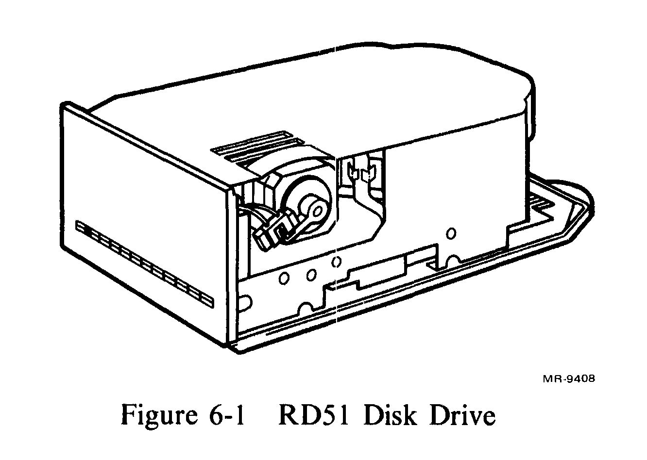
“The RD51 disk drive capacity is 11 megabytes on two nonremovable 133.4 mm (5.25 inch) disks. Each disk surface uses one movable head to service 306 data tracks. The head and disk technology used allows the heads, which normally fly over the disk surface, to land when the drive is powered off. This technology, termed Winchester, utilizes lubricated media and lightly loaded read/write heads.
High bit densities on the media are achieved by flying the heads at a height of 20 microinches. This flying height requires a clean air environment which is achieved by manufacturing and sealing the head and disk assembly (HDA) in a clean room environment.”
The RQDX controllers only work with a very small number of MFM hard drive models. The table below shows the manufacturer’s model number, the physical configuration of these drives, and the RQDX controller that first supported them. Note that a drive model “first supported” on a particular RQDX controller will work with all later RQDX controllers:
| DEC Model |
OEM Model |
First Introduced |
Cylinders | Heads | Sectors | Formatted Capacity |
|---|---|---|---|---|---|---|
| RD50 | Seagate ST-506 |
RQDX1 | 153 | 4 | ?? | 5 MB |
| RD51 | Seagate ST-412 |
RQDX1 | 306 | 4 | 18 | 10 MB |
| RD52 | Quantum D540 |
RQDX1 | 480 | 7 | 18 | 30 MB |
| RD53 | Micropolis 1325 or 1335 |
RQDX2 | 1024 | 8 | 17 | 68 MB |
| RD54 | Maxtor XT-2190 |
RQDX3 | 1224 | 15 | 17 | 152 MB |
| RD31 | Seagate ST-225 |
RQDX3 | 615 | 4 | 17 | 20 MB |
| RD32 | Seagate ST-251 |
RQDX3 | 820 | 6 | 17 | 40 MB |
| RD33 | Microscience HH-1090 |
RQDX3 | 1314 | 7 | 17 | 71 MB |
The RQDX1 and RQDX2 controllers store the drive’s physical configuration parameters in its firmware. By contrast, the RQDX3 instead stores the configuration information on the drive itself. This is one reason why an MFM hard drive must be reformatted when moving it between various models of RQDX controllers, even if the drive is supported by both controllers.
Note that Lou has produced a modified version of the XXDP disk-formatting program that will allow you to format other (non-DEC-configuration) MFM hard drives for use on the RQDX controllers. This opens up the possiblity of using a much broader range of MFM hard drives with your PDP-11. At the time of writing, I’ve not yet checked out this option. This webpage describes Lou’s work
I have chosen to focus my attention on the ST-225 (RD31) and ST-251 (RD32) models. This is because at the time of writing (June 2014), these models can still be obtained fairly readily at reasonable (as well as unreasonable!) prices on eBay. Unfortunately however these drives do not seem to have aged very well. My experience has been that drives selected at random on eBay have about a 20% chance of working well enough to be able to be formatted and used on an RQDX controller. I’ve purchased about 10 drives. From those purchases I have one ST-225 and one ST-251 that I consider to have a sufficiently low number of defective tracks. It may be well worth paying a reasonable premium for a “tested working” MFM hard drive, if the seller provides details of what test he/she has run on the drives, and what the actual test results were.
Important note: An RQDX3 with a “Microcode Version” of 2 is unable to format an ST-225 (RD31) using ZRQCH0.BIN. I was able to successfully format the same drive on a different RQDX3 with a Microcode Version of 4. The Microcode Version gets reported to the console during the format operation.
Testing MFM Hard Drives
The XXDP utilities for formatting (to be discussed later) do not provide any diagnostic information about the health of an MFM hard drive. Instead, they just report whether the formatting operations was successful or unsuccessful.
XXDP does provide some “Exerciser” programs that can be used for doing simple diagnostic tests. The version for the RQDX1 or RQDX2 is ZRQAH0. The version for the RQDX3 is ZRQDA0. Some basic documentation for the XXDP diagnostic programs is available at the Downloads sections below.
Here is the dialogue of a sample session showing ZRQDA0 exercising an ST-251 (RD32) connected to an RQDX3 controller:
STILL NEED TO COMPLETE THIS SECTION. SHOW AN XXDP SESSION. ALSO TALK ABOUT USING SSTOR ON A PC.
Formatting an MFM Hard Drive
To use an MFM hard drive with an RQDX controller, the drive must first be formatted on the RQDX controller using an XXDP program. An MFM hard drive formatted on a PC will not be useable on an RQDX controller, until it has been reformatted on an RQDX controller. It can’t be formatted on a PC and then directly used on the RQDX controller. Further, the drive must be formatted on the same type of RQDX controller that you intend to operate the drive on later. For example, you can’t format the drive on an RQDX2 and then expect to use it on an RQDX3. This is because the RQDX controllers held the drive geometry on-board, and the RQDX3 controllers store the drive geometry on the drive itself. It should be possible to use one controller to format the drive, and another controller to later operate the drive on, if they are of the same type. I’ve not yet tried this.
To format the MFM drive on the RQDX controller we use XXDP programs. For the RQDX1 or RQDX2, use ZRQBC1. For the RQDX3, use ZRQCF0.
Here is the dialogue of a sample session showing ZRQCH0 formatting an ST-225 (RD31) drive. The boot disk was an XXDP 2.5 RX50 disk in drive DU1 (a 3.5-inch floppy drive):
BOOTING FROM  DU1


BOOTING UP XXDP-XM EXTENDED MONITOR


XXDP-XM EXTENDED MONITOR - XXDP V2.5
REVISION: F0
BOOTED FROM DU1
124KW OF MEMORY
NON-UNIBUS SYSTEM

RESTART ADDRESS: 152000
TYPE "H" FOR HELP !

.R ZRQCH0 ↵
ZRQCH0.BIN

DRSSM-G2
ZRQC-H-0
RQDX3 Disk Formatter Utility
UNIT IS Formattable Winchester (RDnn) or Floppy (RX33) Drives
RSTRT ADR 145702
DR>START ↵

CHANGE HW (L)  ? Y ↵

# UNITS (D)  ? 1 ↵

UNIT 0
Enter controller IP Address (O)  172150 ? ↵
What unit do you want to format [0-255] (D)  0 ? ↵
Would you like to revector a single LBN only [Y/N] (L) N ? ↵
Do you want to use the "AUTOFORMAT" Mode [Y/N] (L) Y ? N ↵


Would you like to use the RCT - Revector known bad blocks [Y/N] (L) N ? ↵


                       **** WARNING ****

         ALL DATA ON SELECTED DRIVE WILL BE DESTROYED

         Write protect all drives not being formatted.
         Please verify that the selected drive is ON LINE
         and NOT write protected.

         If formatting RX33 media, insert media to be
         formatted in the selected drive.

Do you wish to continue [Y/N] (L) Y ? ↵


MSCP Controller Model:  19
    Microcode Version:   4

Do you want to use manufacturing bad block information [Y/N] (A) N ? ↵

Downline load UIT [Y/N] (A) Y ? ↵


 UIT  Drive Name
_______________________________________________________
  0   RD51
  1   RD52 part # 30-21721-02 (1 light on front panel)
  2   RD52 part # 30-23227-02 (2 lights on front panel)
  3   RD53
  4   RD31
  5   RD54
  6   RD32
  7   RD33

Enter Unit Identifier Table (UIT) [0-7] (D)  ? 4 ↵

Continue if bad block information is inaccessible [Y/N] (A) N ? Y ↵

Please type in the serial number [8-10 digits] (A)  ? 00000001 ↵


Formatting of Drive 0 Begun.


Format Completed.

00059 Rev LBNs
00000 Bad RBNs
00000 Bad DBNs
00000 Bad XBNs
00059 retired

FCT was not used.

Drive 0 has been formatted successfully.

ZRQC EOP    1
    0 TOTAL ERRS

DR>EXIT ↵

.
As can be seen above, we now have a successfully formatted ST-225 (RD31) drive, ready for use. This process takes about 12 minutes if there are only a few bad LBNs. If the drive has a significant number of bad LBNs, it can take a lot longer (perhaps 3 times as long when there are 60 bad LBNs).
Note that the results section above tells us that this drive has 59 faulty LBNs (although it doesn’t tell us the location of the faulty LBNs). The RQDX3 sets aside space for 100 spare LBNs on an ST-225 (RD31), and 200 spare LBNs on an ST-251 (RD32). So this drive has now used up 59 of the 100 reserve LBNs.
Note that the “UIT” list shown above is quite interesting. It suggests that my RQDX3 does not support the RD50 (as it is not included in the above list), and it instead supports an “RD33” drive. I believe the RD33 geometry is 1170 cylinders, 7 heads, 17 sectors (total = 68MB) but I haven’t verified this.
WARNING: Sometimes ZRQCH0 will return the message “Drive 0 has been formatted successfully” even when the formatting operation failed! I experienced this with an RD31 (ST-225). ZRQCH0 was busy attempting to format the drive for 40 minutes. The drive was making the usual seek noises during this operation, and all seemed normal except for the long time period. At the end of it, ZRQCH0 reported that “Drive 0 has been formatted successfully”. However, it did NOT print out the usual 5 lines of statistics, so there was no way of knowing how many “Rev LBNs” there were. I was unable to “INITIALIZE/BADBLOCKS” this drive under RT-11. When I subsequently ran ZRQGC0 (to check on the health of the MFM drive), it reported that the “Logical blocks per track” was 0. So please be aware of this when interpreting the “success” message you receive from ZRQCH0.
We now need to “INITIALIZE” the freshly formatted ST-225 (RD31) hard drive. So reboot the PDP-11 in RT-11. My boot disk is RT-11 v5.03 on an RX50 disk in drive DU1 (a 3.5-inch floppy drive). First I will create the directory using the “INITIALIZE/BADBLOCKS” command. Then I will issue the “DIR” command, to show that we now have a FORMAT’d and INITIALIZE’d ST-225 (RD31) hard drive:
BOOTING FROM DU1
RT-11SJ  V05.03

.INITIALIZE/BADBLOCKS DU0: ↵
DU0:/Initialize; Are you sure? Y ↵
?DUP-I-No bad blocks detected DU0:
Volume contains protected files; Are you sure? Y ↵

.DIR DU0: ↵


 0 Files, 0 Blocks
 41492 Free blocks

.
This INITIALIZE task takes approximately 3 minutes. You now have a useable ST-225 (RD31) hard drive that was FORMAT’d in XXDP and INITIALIZE’d in RT-11.
Installing RT-11 on your MFM Hard Drive
RT-11 can be installed on your FORMAT’d and INITIALIZE’d MFM Hard Drive with the assistance of “Will’s MSDOS TU58 Emulator” running on a PC. The TU58 was a small tape drive that connected to a PDP-11 via a serial port. With an MSDOS PC connected to the PDP-11 via an RS232 cable, you can boot RT-11 on the PDP-11 from the TU58 emulator, and copy RT-11 from the TU58 emulator to your MFM Hard Drive.
The process for connecting the PDP-11 to Will’s MSDOS TU58 Emulator is as follows:
- Install Will’s MSDOS TU58 Emulator on an MSDOS-based PC.
- Configure the TU58 emulator to serve up an RT-11 image at 38,400 baud, or the highest baud rate supported by your PDP-11 (for example the serial port on the M8189 only supports baud rates up to 19,200). The RT-11 image that I am using is V05.03.
- Configure the PDP-11’s serial port for the same baud rate as used by the TU58 emulator.
- Connect the PDP-11’s serial port to the PC’s serial port.
- Start the emulator on the PC.
- Boot device “DD0” on the PDP-11. This will boot RT-11 from the TU58 Emulator
The downloadable “.arc” file containing the TU58 emulator includes a text file that has instructions for configuring and using the emulator (see the file “rt11arc.txt”).
This other page of mine has instructions for creating an RT-11 image file for use with the TU58 emulator. [INSERT LINK TO PAGE DESCRIBING THIS PROCESS]
First we copy all the RT-11 files from the TU58 emulator accross to the MFM hard drive:
BOOTING FROM DD0
RT-11SJ  V05.03

.COPY/SYSTEM DD0: DU0: ↵
 Files copied:
DD0:SWAP.SYS   to DU0:SWAP.SYS
DD0:RT11AI.SYS to DU0:RT11AI.SYS
DD0:RT11PI.SYS to DU0:RT11PI.SYS
DD0:RT11BL.SYS to DU0:RT11BL.SYS
DD0:RT11SJ.SYS to DU0:RT11SJ.SYS
DD0:RT11FB.SYS to DU0:RT11FB.SYS
DD0:RT11XM.SYS to DU0:RT11XM.SYS
DD0:CR.SYS     to DU0:CR.SYS
DD0:CT.SYS     to DU0:CT.SYS
DD0:DD.SYS     to DU0:DD.SYS
DD0:DL.SYS     to DU0:DL.SYS
DD0:DM.SYS     to DU0:DM.SYS
DD0:DP.SYS     to DU0:DP.SYS
DD0:DS.SYS     to DU0:DS.SYS
DD0:DT.SYS     to DU0:DT.SYS
DD0:DU.SYS     to DU0:DU.SYS
DD0:DW.SYS     to DU0:DW.SYS
DD0:DX.SYS     to DU0:DX.SYS
DD0:DY.SYS     to DU0:DY.SYS
DD0:DZ.SYS     to DU0:DZ.SYS
DD0:PD.SYS     to DU0:PD.SYS
DD0:RF.SYS     to DU0:RF.SYS
DD0:RK.SYS     to DU0:RK.SYS
DD0:LD.SYS     to DU0:LD.SYS
DD0:LP.SYS     to DU0:LP.SYS
DD0:LS.SYS     to DU0:LS.SYS
DD0:MM.SYS     to DU0:MM.SYS
DD0:MS.SYS     to DU0:MS.SYS
DD0:MT.SYS     to DU0:MT.SYS
DD0:NL.SYS     to DU0:NL.SYS
DD0:PC.SYS     to DU0:PC.SYS
DD0:PI.SYS     to DU0:PI.SYS
DD0:SL.SYS     to DU0:SL.SYS
DD0:SLMIN.SYS  to DU0:SLMIN.SYS
DD0:SP.SYS     to DU0:SP.SYS
DD0:TT.SYS     to DU0:TT.SYS
DD0:VM.SYS     to DU0:VM.SYS
DD0:XC.SYS     to DU0:XC.SYS
DD0:XL.SYS     to DU0:XL.SYS
DD0:DDX.SYS    to DU0:DDX.SYS
DD0:DLX.SYS    to DU0:DLX.SYS
DD0:DMX.SYS    to DU0:DMX.SYS
DD0:DUX.SYS    to DU0:DUX.SYS
DD0:DWX.SYS    to DU0:DWX.SYS
DD0:DXX.SYS    to DU0:DXX.SYS
DD0:DYX.SYS    to DU0:DYX.SYS
DD0:DZX.SYS    to DU0:DZX.SYS
DD0:LDX.SYS    to DU0:LDX.SYS
DD0:LPX.SYS    to DU0:LPX.SYS
DD0:LSX.SYS    to DU0:LSX.SYS
DD0:MMX.SYS    to DU0:MMX.SYS
DD0:MSX.SYS    to DU0:MSX.SYS
DD0:MTX.SYS    to DU0:MTX.SYS
DD0:NCX.SYS    to DU0:NCX.SYS
DD0:NLX.SYS    to DU0:NLX.SYS
DD0:NQX.SYS    to DU0:NQX.SYS
DD0:PIX.SYS    to DU0:PIX.SYS
DD0:RKX.SYS    to DU0:RKX.SYS
DD0:SLX.SYS    to DU0:SLX.SYS
DD0:SPX.SYS    to DU0:SPX.SYS
DD0:VMX.SYS    to DU0:VMX.SYS
DD0:XCX.SYS    to DU0:XCX.SYS
DD0:XLX.SYS    to DU0:XLX.SYS
DD0:STARTA.COM to DU0:STARTA.COM
DD0:STARTF.COM to DU0:STARTF.COM
DD0:STARTS.COM to DU0:STARTS.COM
DD0:STARTX.COM to DU0:STARTX.COM
DD0:PIP.SAV    to DU0:PIP.SAV
DD0:DUP.SAV    to DU0:DUP.SAV
DD0:DIR.SAV    to DU0:DIR.SAV
DD0:IND.SAV    to DU0:IND.SAV
DD0:RESORC.SAV to DU0:RESORC.SAV
DD0:EDIT.SAV   to DU0:EDIT.SAV
DD0:K52.SAV    to DU0:K52.SAV
DD0:KED.SAV    to DU0:KED.SAV
DD0:KEX.SAV    to DU0:KEX.SAV
DD0:MACRO.SAV  to DU0:MACRO.SAV
DD0:CREF.SAV   to DU0:CREF.SAV
DD0:LINK.SAV   to DU0:LINK.SAV
DD0:LIBR.SAV   to DU0:LIBR.SAV
DD0:FILEX.SAV  to DU0:FILEX.SAV
DD0:SRCCOM.SAV to DU0:SRCCOM.SAV
DD0:BINCOM.SAV to DU0:BINCOM.SAV
DD0:SLP.SAV    to DU0:SLP.SAV
DD0:DUMP.SAV   to DU0:DUMP.SAV
DD0:SIPP.SAV   to DU0:SIPP.SAV
DD0:BUP.SAV    to DU0:BUP.SAV
DD0:PAT.SAV    to DU0:PAT.SAV
DD0:HELP.SAV   to DU0:HELP.SAV
DD0:SYSMAC.SML to DU0:SYSMAC.SML
DD0:BATCH.SAV  to DU0:BATCH.SAV
DD0:ERROUT.SAV to DU0:ERROUT.SAV
DD0:QUEMAN.SAV to DU0:QUEMAN.SAV
DD0:FORMAT.SAV to DU0:FORMAT.SAV
DD0:SETUP.SAV  to DU0:SETUP.SAV
DD0:VTCOM.SAV  to DU0:VTCOM.SAV
DD0:SPEED.SAV  to DU0:SPEED.SAV
DD0:DATIME.SAV to DU0:DATIME.SAV
DD0:DATIME.COM to DU0:DATIME.COM
DD0:LET.SAV    to DU0:LET.SAV
DD0:SPLIT.SAV  to DU0:SPLIT.SAV
DD0:UCL.SAV    to DU0:UCL.SAV
DD0:VBGEXE.SAV to DU0:VBGEXE.SAV
DD0:TERMID.SAV to DU0:TERMID.SAV
DD0:QUEUE.REL  to DU0:QUEUE.REL
DD0:RTMON.REL  to DU0:RTMON.REL
DD0:SPOOL.REL  to DU0:SPOOL.REL
DD0:VTCOM.REL  to DU0:VTCOM.REL
DD0:TRANSF.SAV to DU0:TRANSF.SAV
DD0:TRANSF.TSK to DU0:TRANSF.TSK
DD0:TRANSF.EXE to DU0:TRANSF.EXE
DD0:GIDIS.SAV  to DU0:GIDIS.SAV
DD0:ALPH00.FNT to DU0:ALPH00.FNT
DD0:ODT.OBJ    to DU0:ODT.OBJ
DD0:VDT.OBJ    to DU0:VDT.OBJ
DD0:VTMAC.MAC  to DU0:VTMAC.MAC
DD0:VTHDLR.OBJ to DU0:VTHDLR.OBJ
DD0:SYSLIB.OBJ to DU0:SYSLIB.OBJ
DD0:PUTSTR.FOR to DU0:PUTSTR.FOR
DD0:GETSTR.FOR to DU0:GETSTR.FOR
DD0:MDUP.SAV   to DU0:MDUP.SAV
DD0:MBOOT.BOT  to DU0:MBOOT.BOT
DD0:MBOT16.BOT to DU0:MBOT16.BOT
DD0:MSBOOT.BOT to DU0:MSBOOT.BOT
DD0:MDUP.MM    to DU0:MDUP.MM
DD0:MDUP.MS    to DU0:MDUP.MS
DD0:MDUP.MT    to DU0:MDUP.MT
DD0:DEMOBG.MAC to DU0:DEMOBG.MAC
DD0:DEMOFG.MAC to DU0:DEMOFG.MAC
DD0:DEMOX1.MAC to DU0:DEMOX1.MAC
DD0:DEMOF1.FOR to DU0:DEMOF1.FOR
DD0:DEMOED.TXT to DU0:DEMOED.TXT
DD0:SAMPLE.KED to DU0:SAMPLE.KED
DD0:VERIFY.COM to DU0:VERIFY.COM
DD0:IVP.COM    to DU0:IVP.COM
DD0:IVP.MAC    to DU0:IVP.MAC
DD0:MTB.COM    to DU0:MTB.COM
DD0:FB.MAC     to DU0:FB.MAC
DD0:SJ.MAC     to DU0:SJ.MAC
DD0:XM.MAC     to DU0:XM.MAC
DD0:BSTRAP.MAC to DU0:BSTRAP.MAC
DD0:EDTGBL.MAC to DU0:EDTGBL.MAC
DD0:KMON.MAC   to DU0:KMON.MAC
DD0:KMOVLY.MAC to DU0:KMOVLY.MAC
DD0:MTTEMT.MAC to DU0:MTTEMT.MAC
DD0:MTTINT.MAC to DU0:MTTINT.MAC
DD0:RMONFB.MAC to DU0:RMONFB.MAC
DD0:RMONSJ.MAC to DU0:RMONSJ.MAC
DD0:TRMTBL.MAC to DU0:TRMTBL.MAC
DD0:USR.MAC    to DU0:USR.MAC
DD0:XMSUBS.MAC to DU0:XMSUBS.MAC
DD0:BA.MAC     to DU0:BA.MAC
DD0:CR.MAC     to DU0:CR.MAC
DD0:CT.MAC     to DU0:CT.MAC
DD0:DD.MAC     to DU0:DD.MAC
DD0:DL.MAC     to DU0:DL.MAC
DD0:DM.MAC     to DU0:DM.MAC
DD0:DP.MAC     to DU0:DP.MAC
DD0:DS.MAC     to DU0:DS.MAC
DD0:DT.MAC     to DU0:DT.MAC
DD0:DU.MAC     to DU0:DU.MAC
DD0:DW.MAC     to DU0:DW.MAC
DD0:DX.MAC     to DU0:DX.MAC
DD0:DY.MAC     to DU0:DY.MAC
DD0:DZ.MAC     to DU0:DZ.MAC
DD0:EL.MAC     to DU0:EL.MAC
DD0:LD.MAC     to DU0:LD.MAC
DD0:LP.MAC     to DU0:LP.MAC
DD0:LS.MAC     to DU0:LS.MAC
DD0:NC.MAC     to DU0:NC.MAC
DD0:NI.MAC     to DU0:NI.MAC
DD0:NL.MAC     to DU0:NL.MAC
DD0:NQ.MAC     to DU0:NQ.MAC
DD0:PC.MAC     to DU0:PC.MAC
DD0:PD.MAC     to DU0:PD.MAC
DD0:RF.MAC     to DU0:RF.MAC
DD0:RK.MAC     to DU0:RK.MAC
DD0:SP.MAC     to DU0:SP.MAC
DD0:TJ.MAC     to DU0:TJ.MAC
DD0:TM.MAC     to DU0:TM.MAC
DD0:TS.MAC     to DU0:TS.MAC
DD0:TT.MAC     to DU0:TT.MAC
DD0:VM.MAC     to DU0:VM.MAC
DD0:XC.MAC     to DU0:XC.MAC
DD0:XL.MAC     to DU0:XL.MAC
DD0:FSM.MAC    to DU0:FSM.MAC
DD0:ELCOPY.MAC to DU0:ELCOPY.MAC
DD0:ELINIT.MAC to DU0:ELINIT.MAC
DD0:ELTASK.MAC to DU0:ELTASK.MAC
DD0:ERRTXT.MAC to DU0:ERRTXT.MAC
DD0:ERROUT.OBJ to DU0:ERROUT.OBJ
DD0:RTBL.MAP   to DU0:RTBL.MAP
DD0:RTSJ.MAP   to DU0:RTSJ.MAP
DD0:RTFB.MAP   to DU0:RTFB.MAP
DD0:RTXM.MAP   to DU0:RTXM.MAP
DD0:SYSGEN.COM to DU0:SYSGEN.COM
DD0:BL.ANS     to DU0:BL.ANS
DD0:SJFB.ANS   to DU0:SJFB.ANS
DD0:XM.ANS     to DU0:XM.ANS
DD0:CONFIG.COM to DU0:CONFIG.COM
DD0:CONFIG.SAV to DU0:CONFIG.SAV
DD0:V5USER.TXT to DU0:V5USER.TXT
DD0:V5NOTE.TXT to DU0:V5NOTE.TXT
DD0:CUSTOM.TXT to DU0:CUSTOM.TXT
DD0:CONSOL.MAC to DU0:CONSOL.MAC
DD0:NITEST.MAC to DU0:NITEST.MAC

.
Next we make the hard drive bootable, by specifying that the RT11 Single-Job Monitor is the file to be loaded when this device is booted:
.COPY/BOOT DU0:RT11SJ.SYS DU0: ↵

.
Finally, we do a DIR to see the files on our MFM hard drive:
.DIR DU0: ↵

SWAP  .SYS    27P 20-Dec-85      RT11AI.SYS    80P 20-Dec-85
RT11PI.SYS    95P 20-Dec-85      RT11BL.SYS    78P 20-Dec-85
RT11SJ.SYS    79P 20-Dec-85      RT11FB.SYS    93P 20-Dec-85
RT11XM.SYS   106P 20-Dec-85      CR    .SYS     3P 20-Dec-85
CT    .SYS     6P 20-Dec-85      DD    .SYS     5P 20-Dec-85
DL    .SYS     4P 20-Dec-85      DM    .SYS     5P 20-Dec-85
DP    .SYS     3P 20-Dec-85      DS    .SYS     3P 20-Dec-85
DT    .SYS     3P 20-Dec-85      DU    .SYS     8P 20-Dec-85
DW    .SYS     5P 20-Dec-85      DX    .SYS     4P 20-Dec-85
DY    .SYS     4P 20-Dec-85      DZ    .SYS     4P 20-Dec-85
PD    .SYS     3P 20-Dec-85      RF    .SYS     3P 20-Dec-85
RK    .SYS     3P 20-Dec-85      LD    .SYS     8P 20-Dec-85
LP    .SYS     2P 20-Dec-85      LS    .SYS     5P 20-Dec-85
MM    .SYS     9P 20-Dec-85      MS    .SYS    10P 20-Dec-85
MT    .SYS     9P 20-Dec-85      NL    .SYS     2P 20-Dec-85
PC    .SYS     2P 20-Dec-85      PI    .SYS    60P 20-Dec-85
SL    .SYS    14P 20-Dec-85      SLMIN .SYS    12P 20-Dec-85
SP    .SYS     6P 20-Dec-85      TT    .SYS     2P 20-Dec-85
VM    .SYS     3P 20-Dec-85      XC    .SYS     4P 20-Dec-85
XL    .SYS     4P 20-Dec-85      DDX   .SYS     5P 20-Dec-85
DLX   .SYS     5P 20-Dec-85      DMX   .SYS     5P 20-Dec-85
DUX   .SYS     9P 20-Dec-85      DWX   .SYS     5P 20-Dec-85
DXX   .SYS     4P 20-Dec-85      DYX   .SYS     4P 20-Dec-85
DZX   .SYS     4P 20-Dec-85      LDX   .SYS     8P 20-Dec-85
LPX   .SYS     2P 20-Dec-85      LSX   .SYS     5P 20-Dec-85
MMX   .SYS    10P 20-Dec-85      MSX   .SYS    11P 20-Dec-85
MTX   .SYS     9P 20-Dec-85      NCX   .SYS     9P 20-Dec-85
NLX   .SYS     2P 20-Dec-85      NQX   .SYS     7P 20-Dec-85
PIX   .SYS    68P 20-Dec-85      RKX   .SYS     3P 20-Dec-85
SLX   .SYS    16P 20-Dec-85      SPX   .SYS     6P 20-Dec-85
VMX   .SYS     3P 20-Dec-85      XCX   .SYS     4P 20-Dec-85
XLX   .SYS     4P 20-Dec-85      STARTA.COM    61P 20-Dec-85
STARTF.COM     5P 20-Dec-85      STARTS.COM     1P 20-Dec-85
STARTX.COM     8P 20-Dec-85      PIP   .SAV    30P 20-Dec-85
DUP   .SAV    47P 20-Dec-85      DIR   .SAV    19P 20-Dec-85
IND   .SAV    56P 20-Dec-85      RESORC.SAV    25P 20-Dec-85
EDIT  .SAV    19P 20-Dec-85      K52   .SAV    54P 20-Dec-85
KED   .SAV    58P 20-Dec-85      KEX   .SAV    53P 20-Dec-85
MACRO .SAV    61P 20-Dec-85      CREF  .SAV     6P 20-Dec-85
LINK  .SAV    49P 20-Dec-85      LIBR  .SAV    24P 20-Dec-85
FILEX .SAV    22P 20-Dec-85      SRCCOM.SAV    26P 20-Dec-85
BINCOM.SAV    24P 20-Dec-85      SLP   .SAV    13P 20-Dec-85
DUMP  .SAV     9P 20-Dec-85      SIPP  .SAV    21P 20-Dec-85
BUP   .SAV    50P 20-Dec-85      PAT   .SAV    10P 20-Dec-85
HELP  .SAV   132P 20-Dec-85      SYSMAC.SML    60P 20-Dec-85
BATCH .SAV    26P 20-Dec-85      ERROUT.SAV    18P 20-Dec-85
QUEMAN.SAV    15P 20-Dec-85      FORMAT.SAV    24P 20-Dec-85
SETUP .SAV    41P 20-Dec-85      VTCOM .SAV    24P 20-Dec-85
SPEED .SAV     4P 20-Dec-85      DATIME.SAV     4P 20-Dec-85
DATIME.COM     3P 20-Dec-85      LET   .SAV     5P 20-Dec-85
SPLIT .SAV     3P 20-Dec-85      UCL   .SAV    15P 20-Dec-85
VBGEXE.SAV    16P 20-Dec-85      TERMID.SAV     3P 20-Dec-85
QUEUE .REL    14P 20-Dec-85      RTMON .REL     8P 20-Dec-85
SPOOL .REL    11P 20-Dec-85      VTCOM .REL    27P 20-Dec-85
TRANSF.SAV    16P 20-Dec-85      TRANSF.TSK    76P 20-Dec-85
TRANSF.EXE    45P 20-Dec-85      GIDIS .SAV    72P 20-Dec-85
ALPH00.FNT     9P 20-Dec-85      ODT   .OBJ     8P 20-Dec-85
VDT   .OBJ     8P 20-Dec-85      VTMAC .MAC     7P 20-Dec-85
VTHDLR.OBJ     8P 20-Dec-85      SYSLIB.OBJ    54P 20-Dec-85
PUTSTR.FOR     2P 20-Dec-85      GETSTR.FOR     2P 20-Dec-85
MDUP  .SAV    20P 20-Dec-85      MBOOT .BOT     1P 20-Dec-85
MBOT16.BOT     1P 20-Dec-85      MSBOOT.BOT     3P 20-Dec-85
MDUP  .MM     56P 20-Dec-85      MDUP  .MS     56P 20-Dec-85
MDUP  .MT     56P 20-Dec-85      DEMOBG.MAC     2P 20-Dec-85
DEMOFG.MAC     3P 20-Dec-85      DEMOX1.MAC     3P 20-Dec-85
DEMOF1.FOR     2P 20-Dec-85      DEMOED.TXT     1P 20-Dec-85
SAMPLE.KED     4P 20-Dec-85      VERIFY.COM     3P 20-Dec-85
IVP   .COM    16P 20-Dec-85      IVP   .MAC    25P 20-Dec-85
MTB   .COM    14P 20-Dec-85      FB    .MAC     1P 20-Dec-85
SJ    .MAC     1P 20-Dec-85      XM    .MAC     1P 20-Dec-85
BSTRAP.MAC    70P 20-Dec-85      EDTGBL.MAC    33P 20-Dec-85
KMON  .MAC   122P 20-Dec-85      KMOVLY.MAC   216P 20-Dec-85
MTTEMT.MAC    18P 20-Dec-85      MTTINT.MAC    46P 20-Dec-85
RMONFB.MAC   149P 20-Dec-85      RMONSJ.MAC    70P 20-Dec-85
TRMTBL.MAC    19P 20-Dec-85      USR   .MAC    74P 20-Dec-85
XMSUBS.MAC    40P 20-Dec-85      BA    .MAC    21P 20-Dec-85
CR    .MAC    15P 20-Dec-85      CT    .MAC    33P 20-Dec-85
DD    .MAC    27P 20-Dec-85      DL    .MAC    37P 20-Dec-85
DM    .MAC    27P 20-Dec-85      DP    .MAC    11P 20-Dec-85
DS    .MAC    10P 20-Dec-85      DT    .MAC     9P 20-Dec-85
DU    .MAC    94P 20-Dec-85      DW    .MAC    43P 20-Dec-85
DX    .MAC    21P 20-Dec-85      DY    .MAC    23P 20-Dec-85
DZ    .MAC    18P 20-Dec-85      EL    .MAC    17P 20-Dec-85
LD    .MAC    47P 20-Dec-85      LP    .MAC    14P 20-Dec-85
LS    .MAC    35P 20-Dec-85      NC    .MAC    43P 20-Dec-85
NI    .MAC    22P 20-Dec-85      NL    .MAC     3P 20-Dec-85
NQ    .MAC    26P 20-Dec-85      PC    .MAC     5P 20-Dec-85
PD    .MAC    12P 20-Dec-85      RF    .MAC     7P 20-Dec-85
RK    .MAC    12P 20-Dec-85      SP    .MAC    43P 20-Dec-85
TJ    .MAC    32P 20-Dec-85      TM    .MAC    27P 20-Dec-85
TS    .MAC    39P 20-Dec-85      TT    .MAC     7P 20-Dec-85
VM    .MAC    21P 20-Dec-85      XC    .MAC     1P 20-Dec-85
XL    .MAC    28P 20-Dec-85      FSM   .MAC    32P 20-Dec-85
ELCOPY.MAC    15P 20-Dec-85      ELINIT.MAC    16P 20-Dec-85
ELTASK.MAC     9P 20-Dec-85      ERRTXT.MAC     6P 20-Dec-85
ERROUT.OBJ    15P 20-Dec-85      RTBL  .MAP    22P 20-Dec-85
RTSJ  .MAP    22P 20-Dec-85      RTFB  .MAP    30P 20-Dec-85
RTXM  .MAP    33P 20-Dec-85      SYSGEN.COM   230P 20-Dec-85
BL    .ANS     9P 20-Dec-85      SJFB  .ANS     9P 20-Dec-85
XM    .ANS     9P 20-Dec-85      CONFIG.COM    27P 20-Dec-85
CONFIG.SAV     7P 20-Dec-85      V5USER.TXT     3P 20-Dec-85
V5NOTE.TXT    41P 20-Dec-85      CUSTOM.TXT     9P 20-Dec-85
CONSOL.MAC     6P 20-Dec-85      NITEST.MAC    22P 20-Dec-85
 206 Files, 5023 Blocks
 36469 Free blocks

.
Now we’re done. Reboot the PDP-11, selecting DU0 as the boot device. RT-11 should start up and place you at the dot prompt:
BOOTING FROM DU0
RT-11SJ  V05.03

.
Checking the health of an MFM Hard Drive
XXDP 2.5 includes a program that can be used to verify the health of an already formatted MFM hard drive. The program is ZRQGxx
Below is the dialogue showing the use of ZRQGC0 under XXDP 2.5, using the ST-225 (RD31) drive formatted above. As can be seen below, ZRQGxx is a menu-driven program. The following example shows the results of selecting options 2 (Drive Information), 3 (RCT Information), 4 (Data Error List) and 6 (Exit).
.R ZRQGC0 ↵
ZRQGC0.BIN

DRSSM-G2
CZRQG-C-0
RD/RX Disk Summary Diagnostic
UNIT IS RQDXn
RSTRT ADR 145702
DR>START ↵

CHANGE HW (L)  ? Y ↵

# UNITS (D)  ? 1 ↵

UNIT 0
IP Address (O)  172150 ? ↵

Disk summary diagnostic for RD54,53,52,51,32,31,33 and RX50,33 devices.

             You have the following options:

               1 - Controller Information
               2 - Drive Information
               3 - RCT Information
               4 - Data Error List
               5 - Salvage Copy
               6 - Exit

           Enter the desired item number: (D)  ? 2 ↵

Drive information selected.
Now performing 4-step initialization.
4-step initialization was successful.

Which drive would you like to bring online?: (D)  ? 0 ↵

Drive number 0 is online.
Drive type is RD31.

Logical blocks per track:      1560 (Dec).

Volume Serial Number is    188,  20466 (Dec)
Drive is fixed.
Drive is not write protected.

Unit hardware version is          0 (Dec).
Unit software version is          0 (Dec).

Logical blocks per track:        17 (Dec).
Tracks in a group:                4 (Dec).
Groups in a cylinder:             1 (Dec).
RCT size in blocks:               3 (Dec).
Replacement blocks per track:     1 (Dec).
RCT copies per unit:              1 (Dec).

Access command on drive number 0 is successful.
Read command on drive number 0 is successful.

Disk summary diagnostic for RD54,53,52,51,32,31,33 and RX50,33 devices.

             You have the following options:

               1 - Controller Information
               2 - Drive Information
               3 - RCT Information
               4 - Data Error List
               5 - Salvage Copy
               6 - Exit

           Enter the desired item number: (D)  ? 3 ↵

RCT information selected.

Which drive would you like to bring online?: (D)  ? 0 ↵

Drive number 0 is online.
Drive type is RD31.

Logical blocks per track:        17 (Dec).

LBN 0 004200 (O) replaced by non-primary RBN    6. (Cyl   33, Head  0 ,Sec  0)
LBN 0 010234 (O) replaced by non-primary RBN   11. (Cyl   63, Head  2 ,Sec  2)

**There are    2 used Rct entries out of a total  100 available.**
  2 percent of the Replacement Blocks (RBN's) have been used.

Disk summary diagnostic for RD54,53,52,51,32,31,33 and RX50,33 devices.

             You have the following options:

               1 - Controller Information
               2 - Drive Information
               3 - RCT Information
               4 - Data Error List
               5 - Salvage Copy
               6 - Exit

           Enter the desired item number: (D)  ? 4 ↵

Data error list selected.

For which drive would you like Data Error information?: (D)  ? 0 ↵

LBN size 000000 121130 (Oct)
Drive number 0 is online.
Drive type is RD31.

Working... Please wait

Reading LBN 00 006446 (Oct) from drive 0.
LBN 00 010234 (Oct) - invalid header. (Cyl   63, Head  2 ,Sec  2)
Reading LBN 00 015220 (Oct) from drive 0.
Reading LBN 00 023772 (Oct) from drive 0.
Reading LBN 00 032544 (Oct) from drive 0.
Reading LBN 00 041316 (Oct) from drive 0.
Reading LBN 00 050070 (Oct) from drive 0.
Reading LBN 00 056642 (Oct) from drive 0.
Reading LBN 00 065414 (Oct) from drive 0.
Reading LBN 00 074166 (Oct) from drive 0.
Reading LBN 00 102740 (Oct) from drive 0.
Reading LBN 00 111512 (Oct) from drive 0.
Reading LBN 00 120264 (Oct) from drive 0.

Total LBN's with data error status =       1.

Disk summary diagnostic for RD54,53,52,51,32,31,33 and RX50,33 devices.

             You have the following options:

               1 - Controller Information
               2 - Drive Information
               3 - RCT Information
               4 - Data Error List
               5 - Salvage Copy
               6 - Exit

           Enter the desired item number: (D)  ? 6 ↵

PASS ABRTD THS UNIT
CZRQG EOP    1
    0 TOTAL ERRS

DR>EXIT ↵
.
Probably the most useful aspect of ZRQGxx is Option 3 (“RCT Information”). This tells us how many faulty LBNs are on the drive, and how many spare LBNs still exist. Note this varies depending on the drive type. For example, the ST-412 (RD31) has 144 spare LBNs available, the ST-225 (RD31) has 100 spare LBNs available, and the ST-251 has 200 spare LBNs available.
The results from running ZRQGC0 on a less-healthy ST-225 (RD31) are available here. As you can see from those results, this drive has used 86 of the 100 available RBNs. When this drive was formatted with ZRQCH0, it reported that the following:
Format Completed.

00086 Rev LBNs
00000 Bad RBNs
00000 Bad DBNs
00000 Bad XBNs
00086 retired

FCT was not used.

Drive 0 has been formatted successfully.
RX33 – 360RPM or 300RPM ??
When I first put this webpage together, I did not have any “real” RX50 or RX33 drives. I now do (as of October 2015). I have 2 x RX33s, and based on the labelling and PCB markings, it is clear these are re-badged Teac FD-55GFRs. The full model number of mine is FD-55GFR-557-U. However, it is quite possible that other FD-55GFR variants were used from time to time, as I’ve encountered quite a few different TEAC branded variants over the past 10 years.
I can’t be certain what the original jumper settings were on my RX33s. My drives had jumper settings that didn’t make a lot of sense (for example – the DC2 and RY jumpers were BOTH installed). The jumpers on my RX33’s, both in terms of placement and markings, closely resemble this diagram (extracted from page 7 of a document I found online titled “Teac FD-55GFR 1.2MB floppy.pdf”). That diagram is supposed to relate to -340, -440 and -540 FD-55GFRs, but it seems to also apply to the -557-U. That same document says that the “strap settings at shipment” were D1, U1, DC2, II & FG. I used these same settings, except that I removed Jumper II and instead installed Jumper I, so I can slow the drive down (from 360RPM to 300RPM) when I pull Pin 2 to GND.
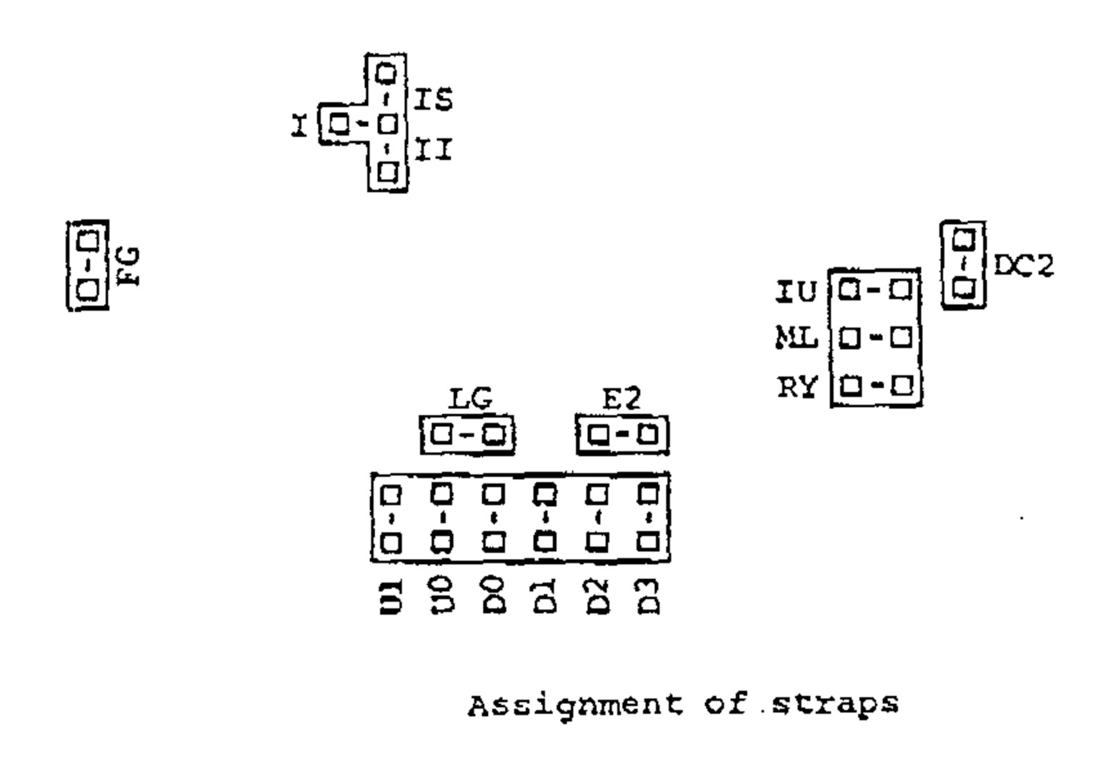
With the jumper settings as described above, and with Pin 2 floating high (so that the RX33 is not forced into 300RPM mode), I confirmed that the RX33 is spinning at 360RPM.
This then raises an interesting question for us: Does the RQDX3 require a 360RPM drive, or is it happy to work with a 300RPM drive? If you are planning on using a PC-era non-DEC 5.25″ 1.2MB “high density” drive with the RQDX3, this is not a problem, because those 5.25″ drives always spin at 360RPM in HD mode. However, if you are planning to use a 3.5″ 1.44MB “high density” drive with the RQDX3, this normally would be a problem because the INDEX pulses (from the PC 3.5″ drive) would be 200msec apart, compared to the 167msec timing that the RQDX3 expects to receive from the RX33.
Fortunately for us, the RQDX3 is very relaxed about this – it doesn’t care whether the RX33-lookalike-drive is spinning at 300 or 360RPM. So the easiest option here is to leave the PC 3.5″ drive in its standard configuration, and operate it at 300RPM. Of course, if you choose this option, it is important that the disk is also formatted at 300RPM.
The RQDX3 will however also allow us to operate our 3.5″ PC-compatible drives at 360RPM, if we chose to do so. The data rate won’t be adjusted (at the RQDX3 end) though, so this option will only work if the disk was formatted and written to at 360RPM. But more importantly, only a small number of PC-compatible 3.5″ drives are capable of operating at 360RPM anyway. The Teac FD-235HG and Panasonic JU-256A are example of drives that are capable of operating at this increased speed (and decreased capacity). They go into 360RPM mode when Pin 2 is pulled low. For this reason, there is a jumper on my RQDX BOB that allows you to do this. Some other drives (notably the Samsung SFD-321B) are capable of 360RPM if you open the drive up and move a surface-mount zero-ohm resistor. The Samsung drive allows you to make the 360RPM change “permanent”, or alternatively, to make the drive operate at 300 or 360RPM depending on the input signal on Pin 2.
Floppy Pin 34 – Ready (L) or Disk Change (L) ??
Early floppy drives (including a real RX50) use Pin 34 as an active-low READY signal. The READY signal, when low, typically means that the drive is selected, the disk is inserted, and the drive is spinning at its operating speed. A FDC would typically not attempt to read data from a floppy disk unless the READY signal was low.
Unfortunately this all changed with the arrival of the IBM PC. The PC expects Pin 34 to be an active-low “Disk Change” signal. What happens is that when the drive is selected, the drive pulls this DC signal low, if the disk has been changed since the drive was last accessed. The drive will (whilst selected) keep the DC line low until the controller sends the drive a “Step” pulse. The drive will then, if a disk is inserted, release the DC line and let it float high. This quirky behavious was added so that the operating system could detect when the user had changed the disk – so that it didn’t inadvertently read or write data from the “wrong” disk. What happens is that a FDC expects that the user has changed the disk, if this signal is low, and the FDC will in response send a “Step” pulse to the drive to try to clear this DC warning.
The RQDX2 always expects Pin 34 to be used as a READY(L) signal. This is of course not a problem when using a real RX50 drive. But if we want to use a PC-era floppy drive (which uses Pin 34 as a DC(L) signal) with the RQDX2, we must either:
- Configure the drive so that Pin 34 is instead used as READY(L), rather than as DC(L). Note however that very few 3.5″ drives allow Pin 34 to be configured in this way. The only such drive I am aware of is the Samsung SFD-321B, which allows this configuration change to be made by moving surface-mount zero ohm links on the PCB. Of course, once this modification has been made, the drive can no longer be used with a PC.
- Put some circuitry between the drive and the RQDX2 to “fake” the ready signal. My RQDX BOB achieves this by providing jumper-selectable options to pull the READY(L) line low when either Drive Select A and/or Drive Select B are low. This means that we are telling the RQDX2 that the drive is ready, even if it is not. So this will cause other errors, if in fact the drive is not connected, the disk is not inserted, etc. But it is the only easy way to handle this problem, without making internal changes to the disk drive.
The RQDX3 does things quite differently. It first attempt to detect whether a “real” RX50 is attached. It does this by seeing if the TRACK00(L) signal gets inhibited (by the drive) when the controller attempts to access the second-side of the RX50. If the controller continues to see an active TRACK00(L) on the second side of the drive, it assumes the drive uses Pin 34 as a DC(L) signal, rather than as a READY(L) signal, and the controller adjusts its expectations of what to see on this line accordingly. So the good news here is that if you are using a PC-compatible 3.5″ drive to emulate an RX50 or RX33 drive, then the RQDX3 will have no issue with Pin 34 being used as a DC(L) signal.
In fact, if you try to connect a drive that uses Pin 34 as a READY(L) signal to an RQDX3 controller, the drive will NOT work with the RQDX3 unless you add circuitry to inhibit the TRACK00 signal when the second side of the drive is selected. This scenario is not likely to arise with a 3.5″ drive (as they seemingly all use Pin 34 as a DC(L) signal). But if you are using a 5.25″ drive with the RQDX3, be sure to either configure Pin 34 (on the drive) to be a DC(L) output, or alternatively, disconnect Pin 34 altogether, so the RQDX3 always sees the DC(L) line floating high. My RQDX BOB has a jumper to support this option.
Other Issues
Some drives don’t properly process the index hole. Where I’ve noticed this is with the Teac FD-235HG, when emulating an RX33 (500kb/s, 300RPM, 15×512 bytes sectors). After the index hole, the drive should output Sectors 1, 2, 3, … 13, 14, 15. Instead, the FD-235HG sometimes serves up sectors 9, 10, 11, 12 … 6, 7, 8, or some similar variant of this. I have observed this behaviour using IMD (on the same drive and with the same RX33 disk) on a PC’s on-board FDC, as well as on an AHA-1522A plugged in to the same PC. The FD-235HG seems to write the sectors to the drive in the correct placement, it is just reading them back that is an issue. Note this problem only seems to occur when the FD-235HD is operating at 300RPM. When it is running at 360RPM (by pulling pin 2 low), it serves up the sectors starting with Sector 1. I have seen this problem occur on two different FD-235HG drives.
The drive’s RPM needs to be very accurate. I formatted and wrote an RT-11 V05.03 RX33 3.5″ 300 RPM disk using PUTR on a PC with a Panasonic FD-235HF. The RQDX3 could handle this with some 3.5″ drives, but the FD-235HG simply would not read it at all. I repeated this process a second time, with the same result. I then discovered that the FD-235HF (that was used to format and write to the disk) was spinning at 298 RPM. I suspect this was the problem. When I removed the 3.5″ drive from that PC and replaced it with another 3.5″ drive, then re-formatted and re-built the same floppy disk using PUTR, it then worked fine on the RQDX3 on all drives that I tested.
When using an MFM hard drive with my RQDX breakout board, the MFM drive should have the DS0 jumper in. On a Seagate ST225 (RD31), that is the jumper in the left-most position. However, if you are using the drive in a BA23 chassis, you need to remove the DS0 jumper and instead install the DS2 jumper (which is the third jumper from the left, on the back of a Seagate ST225). This is because the DS0 jumper will conflict with the drive-select lines used by the RX50 drive in a BA23 enclosure.
Good luck!
Downloads
Schematic for RQDX BOB (Revision A dated 24.05.2014)
Bill of Materials for RQDX BOB (Revision A dated 24.05.2014)
Links
RQDX3 Field Maintenance Print Set (Part Number MP-02259-01) (Has schematics for the RQDX3 and the M9058 distribution board)
RQDX3 Controller Module User’s Guide (Part Number EK-RQDX3-UG-001)
Revision History
26 June 2014:
- Posted initial version, with placeholders for future content.
26 May 2015: Significantly updated in the following areas
- Provided details for formatting and installing RT-11 on MFM Hard Drives
- Added short-form index at top of page, and detailed Table of Contents
- Provided a link to the Schematic (Rev A)
- Corrented minor typos
3 November 2015: Added a higher-res picture of the assembled PCB. Added a Bill of Materials to the Downloads section. Modified the “RX33 – 360RPM or 300RPM ??” section to add information about my experience with a real RX33 drive.
28 June 2016: Ported this page over to my new (WordPress-based) website. Added a new “Introduction” section and added a new “RQDX Breakout Board” header below the new introduction.
2 January 2017: Added the new “DEC’s Breakout Boards” section (focused on the M9058)
18 July 2017: Added details of the BA23-A breakout board (in the DEC’s Breakout Boards section)