DEC BC01V Cable

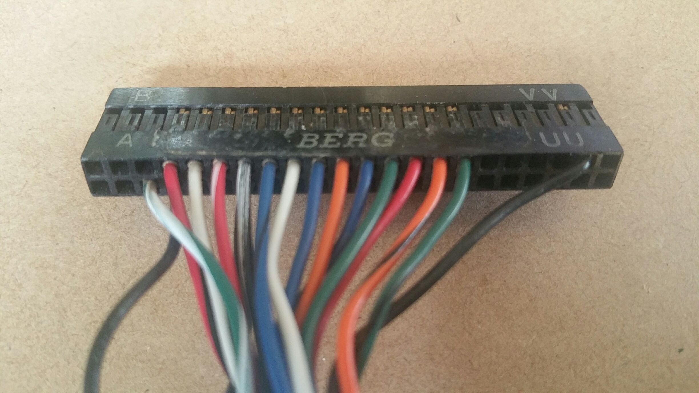
For the PDP-8, the KL8-E (M8650) and KL8-JA (M8655) connect to the outside world via a 40-pin “Berg” connector, arranged as 2 rows of 40 pins as shown here. These boards supports 20mA current loop or RS232 communications, depending on the cable that is connected to it.
This 40-pin connector (or a variant of it) was also subsequently used on some UNIBUS and QBUS PDP-11 systems as well. For example it is used on the UNIBUS DL11-W.
To connect a KL8-E to an RS232 peripheral, DEC specified a DEC BC01V cable. This has a 40-pin Berg female housing on one end (with no mechanical strain relief) and a DB25M on the other end. DEC’s Cables Handbook refers to the 40-pin Berg female housing as being a “H856 connector”.
The BC01V cable is wired as a DTE device, as are VT-series terminals and the serial ports on IBM PC compatibles. So you will usually need a DB25F-to-DB25F “Null Modem” cable to go between the BC01V and the device you want to connect to. The Null Modem cable will swap the relevant wires (eg pin 2 at one end goes to pin 3 at the other end).

Details of the BC01V cable can be found at Page 54 of this PDF of PDP-8/e Engineering Drawings on Bitsavers. A copy of that page is also shown here.
DEC’s BC01V cable is somewhat over-engineered for the KL8-E. It has 15 conductors, when only 3 are required (plus one loop-back jumper wire which is also required). In fact many of the 15 conductors are not supported by the KL8-E. Presumably DEC intended this cable would be used on a variety of other more capable Asychronous Interface boards in the future. The drawing referred to above says that the BC01V was first used on the PDP-8/e. I’ve also used a 25-conductor DEC serial cable with the KL8-E, part number BC05C. It also seems to work fine with the KL8-E.

The pinout diagram for the KL8-E (M8650) is shown here.
If you are connecting the KL8-E to a current loop device (such as an ASR33 Teletype), then Pins H and E need to be connected together in the interface cable. Similarly, if you are connecting the KL8-E to an RS232 device, then Pins M and E need to be connected together instead.
Note that the KL8-E and DL11-W both create fake (always asserted) DTR and RTS signals, and do not support any incoming handshaking or status lines such as DSR, CTS or RI. So it will generally be pointless running these wires in your own home made cables, unless you will be using the cable with a more advanced DEC serial interface board. Keep in mind that you may need to create local loopbacks on some signals at your peripheral, if they are required by the peripheral (eg for the DSR and/or CTS signals).
Minimal RS232 cable: KL8-E to 25-Pin DTE Device

You can easily make a cable to connect the KL8-E directly to a peripheral that has a male 25-Pin DTE RS232 connector on it. For example, this cable will connect the KL8-E directly to a VT100 terminal or to the 25-Pin RS232 connector on the back of an IBM compatible PC, without the need for any “null modem” cable.
The cable shown here uses the AMP 102387-9 housing as a substitute for the Berg connector (further details of this housing are provided below).
This cable is NOT a substitute for the BC01V. Instead, this cable swaps the TXD and RXD wires, so you can connect the cable directly to the peripheral.
Here are the connections required. In the list below: P1 is the Berg female housing, P2 is a female DB25 connector, and signal names are relative to the KL8-E. The pin numbering (1 to 40) shown below assumes you will orient the 40-pin connector so that Pin 1 of the female housing mates with Pin VV of the Berg connector (this is the upper right pin on the Berg housing, when looking into it from the mating side).
- Shield: P1-A (Pin 40) to cable shield
- GND: P1-VV (Pin 1) to P2-7
- RXD: P1-J (Pin 33) to P2-2
- TXD: P1-F (Pin 35) to P2-3
- EIA loop: P1-E (Pin 36) to P1-M (Pin 30)
- [optionally] DTR: P1-DD (Pin 15) to P2-6
- [optionally] RTS: P1-V (Pin 23) to P2-5
I find that a cable length of about 3.0m works well for many applications.
Minimal RS232 cable: KL8-E to 9-Pin DTE Device

You can easily make a cable to connect the KL8-E directly to a USB-to-RS232 adapter that has a male 9-Pin RS232 connector on it. This cable will connect the KL8-E directly to the USB-to-RS232 adapter, without the need for any “null modem” cable.
Here are the connections required. In the list below: P1 is the Berg female housing, P3 is a female DE9 connector, and signal names are relative to the KL8-E.
- Shield: P1-A (Pin 40) to cable shield
- GND: P1-VV (Pin 1) to P3-5
- RXD: P1-J (Pin 33) to P3-3
- TXD: P1-F (Pin 35) to P3-2
- EIA loop: P1-E (Pin 36) to P1-M (Pin 30)
- [optionally] DTR: P1-DD (Pin 15) to P2-6
- [optionally] RTS: P1-V (Pin 23) to P2-8
Substitutes for the Berg housing
The Berg header used by DEC for the BC01V is in fact a 44-pin housing, as shown here. It consists of the 40 pins that are used for signals, plus 2 unused pins at either end of the housing.
It has overall external dimensions of 2.195 by 0.195 inch, and a pin spacing (in both dimensions) of 0.1 inch.
I suspect that genuine Berg connectors and pins are no longer available. So we have to find a suitable substitute when making a new cable.
Option 1: Generic 40-pin housing
A generic 40-pin housing (such as AMP 3-87456-6) will work. But these typically have a nominal external dimension of approximately 2.0 by 0.2 inch, and they can easily be inserted into the Berg connector one pin too far left or right, which is a problem. For this reason, I don’t use standard 40-pin housings to mate with Berg PCB connectors.
Option 2: Amphenol FCI P/N 65043-016LF
This is part of Amphenol’s “Mini-PV” series. Mattis Lind found this part and sent me the link to it. You can find it here on Mouser’s website -> Mouser P/N 649-65043-015LF. It is a 44-pin housing and is $4.91 for a quantity of 1. The contacts for this appear to be Amphenol P/N 48254-000LF, which is Mouser P/N 649-48254-000LF. Element14 carry stock of the contacts, but don’t have stock of the 44-pin version of the housing. I first ordered this product in December 2019 (10 housings and 140 contacts).
Option 3: 44-Pin “AMPMODU Mod IV” Series Connectors by TE Connectivity / AMP
A good substitute for the original Berg connector is the 44-pin housing with part number AMP 3-87456-7 or 3-87456-8. These are shown on TE Connectivity’s Drawing No C-87456. It has nominal dimensions of 2.205 x 0.240 inch. I haven’t yet tried this 44-pin connector, but it should be fine. The 0.240 inch thickness should be no problem (the 40 pin version has the same thickness, and that fits just fine). The problem is that it is somewhat difficult to obtain. Digikey only sell it in minimum of 100 pieces (US$911) and element14 don’t stock it at all. Mouser currently have a small number in stock, but their shipping to Australia is expensive.
So I have gone with the alternative of selecting the 50-pin version. This is AMP 3-87456-9 (without markings) or 4-87456-0 (with markings) and cut it down to make a 44-pin connector. This cut-down connector is what I used on the “KL8-E to 9-Pin DTE Device” cable shown above.
One nice thing about this option is that you can fabricate a loop between vacant holes at either end of the housing, and use that loop as a handle when disconnecting the housing from the board.
Option 4: Another “AMPMODU Mod IV” Series Connector – with different dimensions!
A good option is AMP 102387-9. It is shown on TE Connectivity’s Drawing No C-102387.
This is a 40-pin connector that has a thick wall at either end of the connector. The result is that the overall dimensions are 2.180 x 0.227 inch. It mates with the KL8-E without any risk of misalignment. Another nice thing about this housing is that because there are only 40 holes (rather than 44), there is less risk of mis-counting the holes and clicking the pins into the wrong holes.
This connector is used on the “KL8-E to 25-Pin DTE Device” cable shown above.
This part is currently available from Digikey (P/N A25909-ND) and element14 in small quantities. I have used this connector and it works well for me. The only problem is that it comes with a polarising key on one side, which must be cut off.
Pins for “AMPMODU Mod IV” Series Connectors
I’ve been using the following:
- AMP TE-Connectivity P/N 1-141708-2 (element14 P/N 2499385). These suit 26 AWG and are $0.714/ea in QTY of 100+. These are the pins I am currently using as at July 2017
- AMP TE-Connectivity P/N 87667-5 (element 14 P/N 973294). These suit 22-26 AWG and are $0.653/ea in QTY of 100+
- 28.07.2017: Digikey has a good option. TE Connectivity’s 87756-4 (Digikey A25669CT-ND) for A$25.47 per 100. Gold plated, 22-26 AWG. I am planning to order these in the future
Crimpers for AMPMODU Mod IV Contacts

The correct crimper for AMPMODU Mod IV connectors is TE Connectivity P/N 58641-1. Unfortunately this is a very expensive tool ($US285 as at July 2017).
I have however found a much cheaper alternative that does an acceptable job. I purchased a set of PA-09 crimpers on eBay, as shown in the picture on the right. These were only about A$62.

The 1.6mm slot on the PA-09 crimper is a good match for the AMPMODU Mod IV pins. The pins crimp nicely, with the ears curled down into the wire (see picture on the right here). The only slight issue is that the width of the tool is such that it only curls about 70% of the length of the main ears. You can see this in the photo shown here on the right. Another point to note is that the ears that crimp over the insulation tend to be splayed in a V-shape before they are crimped. I found that I needed to bend these inwards (to more of a U-shape) using the nose of the crimper, to fit them in the 1.6mm slot.
If you are thinking of buying a PA-09, you may also want to consider the larger PA-21 as an alternative. I don’t yet own a PA-21, but I note that it also has a 1.6mm slot, so it will probably also work acceptably with these contacts.
Useful links
Doug Jones’ page describing the BC01V RS232 Interface Cable
Revision History
6 May 2017: Added diagram showing M8650 signals on the Berg connector. Modified the pin numbering in the cable descriptions to match the new diagram. The previous numbering assumed Pin 1 would mate with Berg Pin A, whereas now I suggest Pin 1 should instead mate with Berg Pin VV, to conform with the physical layout of modern shrouded right-angle male 40-pin headers.
17 January 2017: Posted initial version.
30 July 3017: Added details about the PA-09 crimper. Made minor changes to the information about AMPMODU housings and pins.
16 February 2018: Added the Amphenol P/N 65043-016LF to the list of suitable connectors, after receiving information about it from Mattis Lind.
09 May 2021: Updated cable wiring diagrams to add optional DTR and RTS wiring.