If you are using RT-11 on a PDP-11 that has physical drives that are larger than 32MB, you’ll probably want to know about drive partitioning.
This is because a drive in RT-11 cannot be larger than 65536 blocks (32MB). If the physical drive is larger than that, you won’t be able to access or use the remaining space (beyond the 32MB boundary) unless you set up drive partitions.
Fortunately this is an easy thing to do. It doesn’t involve writing a partition table to the drive. Instead it all seems to be handled within the DU.SYS driver in RT-11.
There are a couple of simple rules to keep in mind:
- Every partition will be exactly 65536 blocks (32MB), except that the last partition on the drive will take up whatever space remains and will therefore be 65536 blocks or less in length.
- There’s no way to setup shorter partitions. For example, you cannot partition a 44MB drive into 4 x 11MB drives.
- When you do a low-level format of a physical drive, that formats the entire disk surface. So after you setup drive partitions, you will not need to do another low-level format. All you need to do is INIT the new partitions that you have not previously used, to write a directory structure to them.
Viewing the existing partition structure
Paritions are set up by pointing DU devices at the relevant portion of the relevant physical drive on the relevant controller board. RT-11 supports eight DU devices (DU0 through DU7) though I think you can expand this number through doing a SYSGEN.
The “default” assignment of DU devices can be seen by issuing a SHOW DEV:DU command on a fresh install of RT-11. Here’s what I get on my system with RT-11 V5.3 installed:
.SHOW DEV:DU ⤶

Device    Status          CSR     Vector(s)
------    ------          ---     ---------
  DU      Resident       172150   154

          DU0: is set UNIT=0, PART=0, PORT= 0
          DU1: is set UNIT=1, PART=0, PORT= 0
          DU2: is set UNIT=2, PART=0, PORT= 0
          DU3: is set UNIT=3, PART=0, PORT= 0
          DU4: is set UNIT=4, PART=0, PORT= 0
          DU5: is set UNIT=5, PART=0, PORT= 0
          DU6: is set UNIT=6, PART=0, PORT= 0
          DU7: is set UNIT=7, PART=0, PORT= 0


.
In the above table, “Port” is the controller number, “Unit” is a physical drive connected to that Port, and “Part” is a partition on that physical drive.
Most systems will only have one MSCP controller (such as an RQDX3 controller – M7555) and therefore only have one “Port”. But by doing a SYSGEN you can setup multiple Ports if you want to.
From the above table we can see that by default DU0 is the first partition of drive 0, DU1 is the first partition of drive 1, etc. This enables us to daisy chain two drives on the one controller and be able to access each drive (at least the first 32MB of it) without the need to configure any DU settings.
Partitioning a large drive
If your drive in greater than 32MB in size, you’ll need to do this unless you are happy to only use the first 32MB.
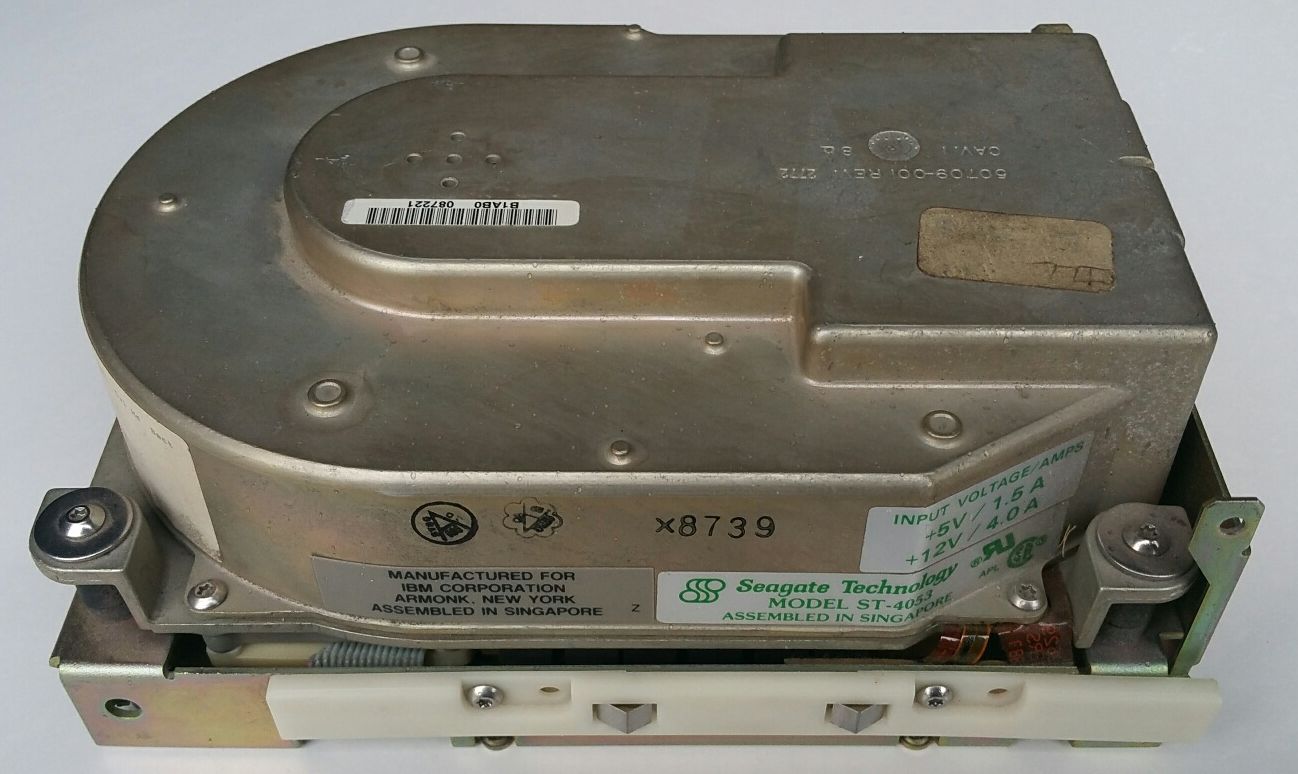
Let’s work through an example. Our system has one hard drive connected to it. It’s a 44MB Seagate ST-4053 MFM drive attached to the PDP-11/23 through a Webster SRQD11-A controller. I’ve previously done the low-level format of the drive using the on-board WOMBAT firmware, and I’ve done an INIT on device DU0 to write a directory structure to DU0 (which is the first 32MB of the ST-4053).
Now we want to be able to access the remaining 12MB of the ST-4053. All we need to do is issue the following commands one time at the RT-11 prompt:
.SET DU1 UNIT=0 ⤶

.SET DU1 PART=1 ⤶

.
If we now issue the SHOW DEV:DU command we get the following:
.SHOW DEV:DU ⤶

Device    Status          CSR     Vector(s)
------    ------          ---     ---------
  DU      Resident       172150   154

          DU0: is set UNIT=0, PART=0, PORT= 0
          DU1: is set UNIT=0, PART=1, PORT= 0
          DU2: is set UNIT=2, PART=0, PORT= 0
          DU3: is set UNIT=3, PART=0, PORT= 0
          DU4: is set UNIT=4, PART=0, PORT= 0
          DU5: is set UNIT=5, PART=0, PORT= 0
          DU6: is set UNIT=6, PART=0, PORT= 0
          DU7: is set UNIT=7, PART=0, PORT= 0


.
See what we’ve done? DU0 is still the first partition (32MB) of the first physical drive attached to the first controller, and DU1 is now the second partition (32MB) of the first physical drive attached to the first controller. Because our physical drive is only 44MB in size, DU1 will only be 12MB.
There’s no need to put these SET commands in your STARTS.COM file or anywhere else. It seems that when we issue the SET commands it perhaps alters the DU.SYS driver file. The changes we’ve made are persistent and will automatically apply each time you reboot. You can test this by rebooting the PDP-11 and reissuing the SHOW DEV:DU command.
If you haven’t already done do, go ahead and reboot now. I think this is necessary so that we reload the DU.SYS driver and apply the changes that we’ve made.
Now we need to INIT device DU1 as follows:
.INIT DU1: ⤶
DU1:/Initialize; Are you sure? Y

.DIR DU1: ⤶


 0 Files, 0 Blocks
 19804 Free blocks

.
OK – we’re done. Note that our DU1 drive has 19804 blocks available (approximately 10MB).
Reference material
The format of the “SET DUx” command is shown at page 227 of the RT-11 Commands Manual (Order Number AA-PDU0A-TC), for RT-11 V5.6.
Revision History
26 July 2016: Posted initial version