
The “Seeburg Red Box” is the electronic control module in a few models of Seeburg jukeboxes made in the late 1970s. The Red Box is of interest to me because it was used in the Seeburg “Topaz” jukebox. The Topaz is a 100-selection (50 record) machine with a sloped front and chrome surround. Quite a nice 1970’s retro look.
We operated about 7 Topaz jukeboxes for party hire in Melbourne, Australia during the period 1986-2005. I’ve hoarded a few of them since those days, and am now slowly getting around to restoring a couple of machines to working condition.
The full schematic for the Red Box is available here -> 19.0MB PNG or 3.6MB JPG.


Overview
The Red Box seems to have initially been called the “CMOS Selector Pricing Unit Type CSP1” though later models are marked as “DEC-MCU Translator Model DMT1”. It’s main purpose is to accept inputs from the coin mechanism, and to queue up songs to play as selections are entered on the keypad. It keeps track of how many credits are available (maximum 15) and reduces the available credits by one each time a selection is made through the keypad. The Red Box doesn’t store the song queue internally. Instead this is done by the “tormat unit” located attached to the main mechanism. The Red Box writes this information into the tormat unit, to tell the tormat unit that the selection is waiting to be played. The tormat unit stores this information in non-volative memory (a series of toroids, working on the same principle as “core memory” in some early computers). There is one toroid per record side, so the tormat unit consists of 100 toroids in total, configured in 2 rows of 50. The toroids for the “A” sides are scanned as the mechanism moves from left-to-right, and the toroids for the “B” sides are scanned as the mechanism moves from right-to-left. Selected songs are played in the order that the mechanism encounters them, rather than in the order that they were entered on the keyboard.
Inside the Red Box you will find 2 single-sided PCBs. The upper PCB is connected to the lower PCB through a few sets of thick conductive pins.
A small pricing-card PCB plugs into the Red Box. This has a series of jumpers which are configured to determine how many credits are added for each coin input. There are 3 coin inputs (Yellow, Green and Red). There is also a “Bonus” jumper. You jumper this so that one (and only one!) of the 3 coin inputs will provide one bonus credit when a second coin of the same type is inserted.
The Red Box is very reliable, but nevertheless faults can and do occur from time to time. There is no microprocessor in it. Instead, it’s just dedicated hard-wired 12-Volt CMOS logic. I have documented below a couple of faults that I have fixed recently.
Fault: “Select” lamp does not work
The “Select” lamp near the keypad is intended to illuminate whenever there is one or more credits, or when the jukebox is on free play. This lamp was not working, and the fault was traced back to the red box.
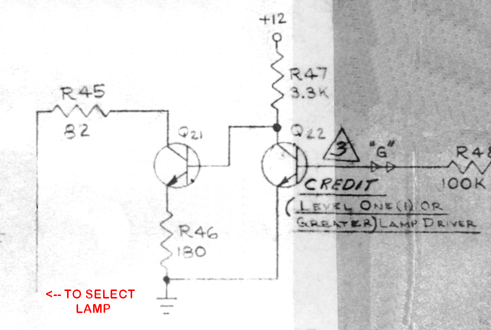
This fault was easy to fix. The relevant part of the circuit is shown to the right here (click on it for a larger version). Q21 is the driver transistor for the lamp. The base-emitter junction is reverse biased by 0.6V (by R46 and R47) to ensure Q21 is off when it is supposed to be off. When the lamp is turned on, current from the +35V rail flows through the globe and a 82R resistor (R45), then into the collector of Q21, then to ground via a 180R emitter resistor (R46). In the on state, the globe has 20V accross it and 51mA flows through it. When the lamp is to be illuminated, current flowing into the base-emitter of junction of Q21 will cause the base voltage to rise from 0.0V to approximately 0.6V. It will also cause much larger current flow in the collector-emitter junction, and the collector voltage will drop from 35V to about 9V. The collector voltage doesn’t drop to 0V due to the presence of the emitter resistor (R46).
A few quick checks with the multimeter verified that the base voltage was rising correctly to 0.6V, but the collector voltage remained at 35V, rather than dropping to 9V. This was fixed by replacing Q21 (originally a TS3563) with a generic NPN signal transistor (BC337). I couldn’t find any data for the TS3563 or any information about recommended replacements. I did find information about a PN3563, but that has a VCEO specification of only 12V and would therefore not be suitable for this application, as VCE in the off state is 35V. Suitable replacements appear to be BC337, 2N3904 or BC547 (not BC548 due to VCEO specification). Check orientation before installing the new transistor. The pinout for the TS3563 and 2N3904 from left to right is E-B-C whereas for the BC337 and BC547 it is C-B-E.
Fault: Jukebox sometimes powers on with credits
In normal operation, the Red Box should clear the credit counter each time the jukebox is turned on. However, I have one Red Box that would, after power on, sometimes have 8 or 15 credits on it.